


I need to know how to wire it up, you'll all know I that I know nothing about wiring after my recent new head unit install - but we got there in the end! This is the last thing to be wired!
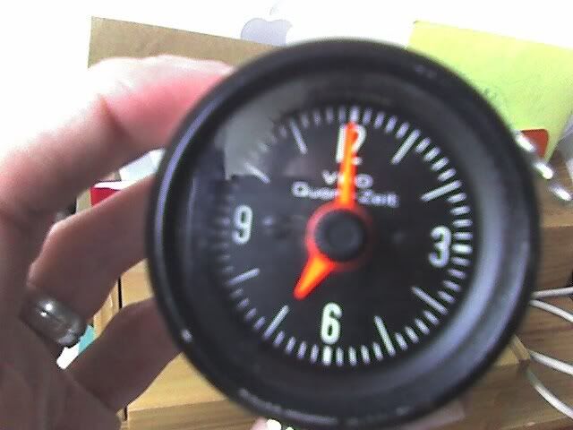
The inscription along the side reads:
477 919 211
218/28/1
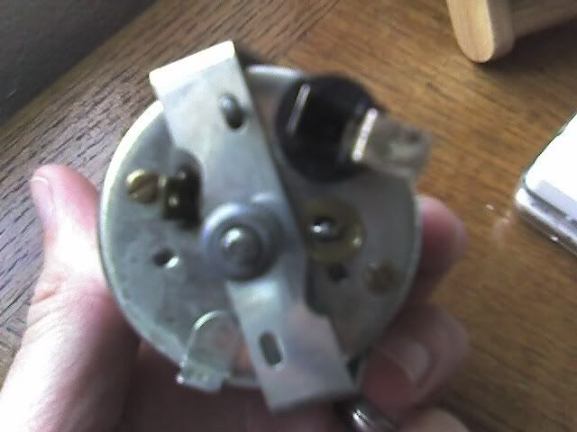
This is the back:
Ok so,
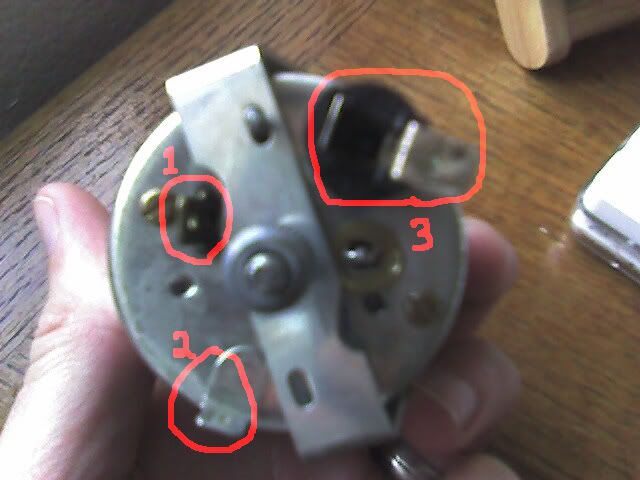
this is what I think - am I right?
1) Power (guessing a 12v wire)
2) Earth
3) Bulb
Now what do I wire to where and with what type of cable?
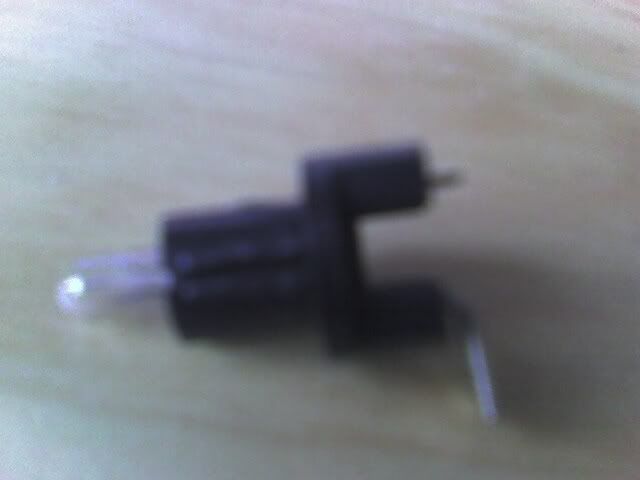
This is a close up of 3 when the bulb is removed with the spade connector on the end.
Ok so that is lots of photos and the inscription on the clock, guessing that is enough to keep you going for the time being! Sorry about quality of photos but the camera is still bust so relying on my Palm.


