ok i have salvaged a typical mini tachometer from another mini and have added it to my 2 dial set now making the classic 3 with a new wallnut dash etc etc. problem is - is that it didnt work after putting everything back together and then testing it - DOHHHH. everying seemed to be installed and conected correctly. funnily enough my original wiring loom actually has the 2 wires (black/white & light-green/orange) left dangling that should connect to the tachmeter - so surely it should be working. my understanding is that the +v comes through from the white/black wire and the positive earth goes out the light-green/orange wire. i even took the casing off the tachometer to test whether the voltage is coming through and it does - all the way through to the earth terminal from the
+v terminal - therefore electrical current must be making its way through the tachometer circuit fine. when testing it i started the car and revved it the voltage fluctuated from just under 12v to just over on my volt meter tester (testing the earth terminal). maybe something is stuck - does anyone know of any typical problems with tachometers in this manner? are there any other ways of testing it such as direct to the battery for ease in testing etc?
cheers
dan


tachometer problems
Started by
danoz24
, Jun 29 2007 09:01 AM
8 replies to this topic
#2

taffy1967
-

- Members
-

- 9,896 posts
Whovian
- Local Club: South Wales Minis
Posted 29 June 2007 - 10:57 AM
Well this subject has been covered and here's one search result: -
The only problem I've encountered with the rev counter on my Mini, was when my wiper motor park-switch failed. So if you're wipers don't park themselves, or only work intermittent, replace you're park-switch, because it runs on the same circuit as you're instruments and heater blower motor and it can either cause that particular fuse to keep blowing or for the gauges to misread.
Well I thought it was worth a mention anyway: -
I've also heard that there can be compatibility issues between instruments used for injection and not injection Minis. Plus Smiths and Nippon Seiki Instruments don't always work well together too?
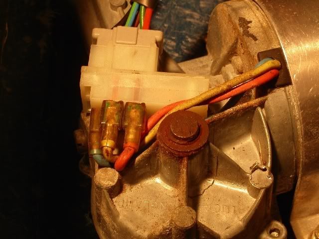
Have another look at the loom. Where you have found that white/black there should also be a green with a spade on the end. These should both be taped together and taped back to the outside of the loom by the multi-plug for the clocks. The other end of the white/black should be hanging around near the coil.
You really need the 3 clock PCB if you are just adding a tacho to an existing 2 clock. The PCB carries the tacho lamp connection and the earth for it too. You can fiddle an earth by fitting an eyelet to some cable and trapping it under the earth screw on the tacho, then do the same at the other end to join it to another earth on the clocks. Fitting the lamp is a lot harder without the pcb, you may be able to solder some leads to the bulb holder and fit one to your new earth jumper and the other solder to the clock lighting track. It is fiddly without the PCB.
The only problem I've encountered with the rev counter on my Mini, was when my wiper motor park-switch failed. So if you're wipers don't park themselves, or only work intermittent, replace you're park-switch, because it runs on the same circuit as you're instruments and heater blower motor and it can either cause that particular fuse to keep blowing or for the gauges to misread.
Well I thought it was worth a mention anyway: -
I've also heard that there can be compatibility issues between instruments used for injection and not injection Minis. Plus Smiths and Nippon Seiki Instruments don't always work well together too?
#3
danoz24
-
- TMF+ Member
-
- 383 posts
Speeding Along Now
Posted 29 June 2007 - 12:27 PM
ok thanks for your help - but, just for testing sake, when connecting the tacho to something like a battery - direct connection - should this prove to work also? should i see the needle move at all? is there any other way i can test whether it is working?
cheers
dan
cheers
dan
#4
Jimmyarm
-

- Members
-
- 2,239 posts
Entrepreneur of Adult Material
- Local Club: TMf
Posted 29 June 2007 - 12:58 PM
What wires are coming out the back of it ? You can just run the positive and feed wires direct from the coil and earth it on the engine etc to see if it works.
#5
danoz24
-
- TMF+ Member
-
- 383 posts
Speeding Along Now
Posted 29 June 2007 - 01:39 PM
ok the terminals from the back of the tacho are 2 in total - 1 being circular (green/orange wire) and the other is a spade shape (white/black wire) the wires i had sitting behind the dash and not connected to anything were the relative colours and had relative factory-crimped female ends according to what is required to connect to the tacho.
can i test the tacho with the engine off then or does it need to be revved up?
cheers
dan
can i test the tacho with the engine off then or does it need to be revved up?
cheers
dan
#6
Jimmyarm
-
- Members
-
- 2,239 posts
Entrepreneur of Adult Material
- Local Club: TMf
Posted 29 June 2007 - 02:30 PM
No you need to turn the engine on, saying that tachos I have seen have more connections than that. There is usually a feed, positive, earth and light power so I don't really know how you could test that one  How does it earth and take its light feed etc ?
How does it earth and take its light feed etc ?
Edited by Jimmyarm, 29 June 2007 - 02:31 PM.
#7
taffy1967
-
- Members
-
- 9,896 posts
Whovian
- Local Club: South Wales Minis
Posted 29 June 2007 - 03:13 PM
The PCB handles the light, like I quoted above from what Dan stated a while back.
#8
Dan
-

- TMF+ Member
-
- 21,354 posts
On Sabbatical
Posted 29 June 2007 - 06:00 PM
The PCB also handles the earth. What you say above about having an understanding Dgnoz24, I'm afraid to say that you don't. Saying there's a positive and then a positive earth is just all wrong.
The two terminals you have found on your tacho are supply and sensing, neither is earth (which is negative). The tacho is an instrument, not just a dumb cicuit device. It runs off the power supplied through the supply and earth and only displays when it senses an intermittant earth connection at the sensing terminal There is a screw on the back of the casing that needs to be connected to the PCB and this is the earth for the instrument. Your tacho is not powered until it has both supply and earth. All this is detailed in the quote that Taffy kindly provided above. A tacho will not work if it's simply plugged in, it needs an input from the ignition for it to sense or it won't display anything. If it just made up a reading for itself what would be the point of it?
The two terminals you have found on your tacho are supply and sensing, neither is earth (which is negative). The tacho is an instrument, not just a dumb cicuit device. It runs off the power supplied through the supply and earth and only displays when it senses an intermittant earth connection at the sensing terminal There is a screw on the back of the casing that needs to be connected to the PCB and this is the earth for the instrument. Your tacho is not powered until it has both supply and earth. All this is detailed in the quote that Taffy kindly provided above. A tacho will not work if it's simply plugged in, it needs an input from the ignition for it to sense or it won't display anything. If it just made up a reading for itself what would be the point of it?
#9
WILLIAMJONES444
-

- Noobies
-
- 9 posts
Just On Tickover
- Location: Cheddleton, Staffs
Posted 28 June 2017 - 02:30 PM
Replace Black & White Tachometer Clock wire from the Ignition Coil and re-feed.
Check park switch wiper-motor connections.
Then replace the black and white wire connection to the clock and check earth screws are in place to the circuit board.
Cut off black and white wire end and fit a bullet connection slot terminal to the clock and hit into the gold pin with a rubber mallet, and then connect the black and white wire from the ignition coil to the clock feed, and then you should have a green and orange wire as well to the clock.
This is a video explaining how I fixed my tachometer connection after fitting a new dashboard, this is a common issue... the main issue is the connection when you pull the wire off the clock gold pin, as the wire gets damaged inside the connection as most people pull it off with pliers as the wire is hard to get off.
Hope this helps
Like the video if this helps:


1 user(s) are reading this topic
0 members, 1 guests, 0 anonymous users


