Jump to content


Photo

Is My Stepper Motor Fried? (tech Details Included...)


  • Please log in to reply
6 replies to this topic

#1 Avl_Paul

Avl_Paul

    Mini Mad

  • Noobies
  • PipPipPipPip
  • 115 posts

Posted 13 January 2008 - 01:49 AM

Stepper Motor Measurement

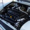
Suspecting that I have a stepper motor issue, I removed the stepper and checked the resistance from the common pin (Pin2) to each other pin (Pins 1, 3, 4, & 6). Resistance was ~15 Ohms to each pin. I then powered each pin w/ 12 VDC - the maximum rotation I achieved from any pin was probably 1/4 rotation at maximum. Shouldn't the stepper rotate multiple times? How is that achieved?

Note, the pin out I used is from the Rover MEMS Chapter 14:

-----------
3 2 1
6 _ 4
------------

Can someone direct me on how to confirm whether I have a fried stepper or if my problem is on the wiring harness end? The solder connections that Sprocket mentions in the Pinned info on Stepper Motors "look" okay but I may need to check them differently. Advice?


Engine Harness Measurements
Before pulling the stepper motor, I also measured the signals going to the stepper (with the stepper connector disconnected). These measurements are on the engine harness connector going to the stepper motor:
Pin 2 to Pin 1: Nominal Battery Voltage Always Present
Pin 2 to Pin 3: ~10 VDC seen briefly during key off
Pin 2 to Pin 6: Nominal Battery Voltage Always Present
Pin 2 to Pin 5: Nothing detected during key on or key off
Pin 2 to Pin 4: 300mV measured consistently during key on

Pin out is the reverse of the stepper motor:
------------
1 2 3
4 _ 6
-------------

Anyone know if this is correct? When I disconnected either connector at the Relay Pack, the voltage at Pin 2 dropped and did not come back up until I key on again. Is the voltage persisting on certain pins because it is still trying to move to a known position?

Would GREATLY appreciate advice at this point? Trying to have the car back together to drive by Monday.

Thanks!

Edited by Avl_Paul, 13 January 2008 - 01:52 AM.


#2 Avl_Paul

Avl_Paul

    Mini Mad

  • Noobies
  • PipPipPipPip
  • 115 posts

Posted 13 January 2008 - 03:09 PM

Partial answer to my own question:

1) Stepper motor is NOT fried: I found a reference article online about stepper motors:

http://www.eio.com/StepperMotors1.pdf

Using that reference, I was able to figure out how to index the stepper motor through to rotate in one direction several times and verified that the plunger extends.

So, now that leaves me with the second part of my question above - are the voltages I am seeing at the connector the stepper motor indicative of a problem with the wiring harness or MEMS unit?

#3 Sprocket

Sprocket

    Great on Injection faults

  • Members
  • PipPipPipPipPipPipPipPipPipPip
  • 7,266 posts
  • Location: Warrington
  • Local Club: Manchester Minis

Posted 13 January 2008 - 05:24 PM

The Rover stepper motors are unipolar. These are normaly 6 wire, but Rover cheekily wired the windings together at the common giving five wires. It is the same thing.

Pin 2 is the common and 12vdc. The ecu grounds the other pins in a certain sequence, so to 'step' the motor by 7 degrees, each step one way or the other (depending on sequence). There are a total of 180 steps for the mechanism.

It will be difficult to measure the voltages as the frequency is something like 8 steps a second, so each winding is pulsed once every second, and for arguments sake, pulsed for 1/8th of a second.

If the winding resistancies are the same from 2-1, 2-3, 2-4, 2-6, and then 1-3, 1-4, 1-6, 3-4, 3-6, 4-6, there wont be much wrong with it.

If when you turn the ignition off, you hear the clicks from the stepper motor, the motor is working. Get a friend to turn the ignition on and then off, as you watch the stepper pin and throttle linkage. You should see this move. it motors full closed then open to a pre set value for the coolant temperature.

Another way is to index the throttle cable. Turn the ignition on (two plug ECUs need a spring on the throttle pedal to hold the throttle switch closed) and from the engine bay, move the throttle linkage full open, you should see and hear the stepper motor movet to a set possition, so you can then adjust the throttle cable. There is a device called the lost motion linkage. It allows a small amount of free play in the mechanism. The cable should be adjusted at this point to ensure the middle prong is in the middle of the other two. If you dont know what part im talking about, if you look at the throttle linkage where it joins to the throttle shaft, when you move the linkage, you can see movement befor the throttle itself moves. This is the lost motion linkage. Once done, turn off the ignition and the stepper will again motor closed and then open again.

Im sure I wrote something about this in the pinned section, lol, I cant remember how much of that I put in there :crazy:

#4 Avl_Paul

Avl_Paul

    Mini Mad

  • Noobies
  • PipPipPipPip
  • 115 posts

Posted 13 January 2008 - 09:26 PM

The stepper motor does NOT turn when you key off - it vibrates back and forth at a high frequency as if some of coils are not being powered down. I'm going to check the wiring to the ECU next.

#5 Sprocket

Sprocket

    Great on Injection faults

  • Members
  • PipPipPipPipPipPipPipPipPipPip
  • 7,266 posts
  • Location: Warrington
  • Local Club: Manchester Minis

Posted 13 January 2008 - 10:22 PM

If that is the case, remove the motor from the housing competely and see if the motor shaft turns freely. There will be a notchy feel to it as the motor contains permanant magnets, each notch would be one step. Check the solder joints on the connection PBC.

If after that, nothing works, its time to get the ECU tested by a specialist im afraid.

#6 Avl_Paul

Avl_Paul

    Mini Mad

  • Noobies
  • PipPipPipPip
  • 115 posts

Posted 14 January 2008 - 12:18 PM

Thanks Sprocket. Yes, the motor shows no signs of bearing wear or sticking when rotated and checks out fine on the bench (I can make it rotate once I figured out the right order of powering the coils). So, if the stepper checks out, that leaves the wiring harness and MEMS unit as possible causes.

Note: when I key on/key off while watching the stepper motor directly - the shaft vibrates back and forth but does NOT turn. It is like it is powering multiple coils at the same instant and fighting itself!!!

I checked continuity on all the wires from the stepper motor to the ECU and all checked out fine per the manual. Lastly, I powered the main relay by grounding Pin4 on the ECU and I then saw NBV at each coil terminal on the stepper. So, it really does look like the problem is the ECU.

Would it still be worth getting the ECU connected to a diagnostic tool before sending off the ECU to an expert?

If I have to send it off, where would you recommend?

#7 BoyracerAU

BoyracerAU

    Mini Mad

  • Members
  • PipPipPipPip
  • 269 posts

Posted 16 March 2008 - 12:39 AM

I'm just curious about something. I've searched high and low, but whilst I can see how to adjust it, I don't actually know what it does.

What is a Lost Motion Linkage? What is it's purpose?


1 user(s) are reading this topic

0 members, 1 guests, 0 anonymous users