Sorry to post a link to my own thread but think my previuos title wasn't getting the response I needed
http://www.theminifo...showtopic=80104
cheers
Ian


Anybody Running A Nippon Denso Alternator
Started by
Udo
, Apr 16 2008 06:51 AM
28 replies to this topic
#1

Udo
-
- Members
-

- 1,670 posts
Camshaft & Stage Two Head
- Location: Lincoln
Posted 16 April 2008 - 06:51 AM
#2
Paul Wiginton
-

- Members
-
- 1,585 posts
Camshaft & Stage Two Head
- Location: at home
#3
Udo
-
- Members
-
- 1,670 posts
Camshaft & Stage Two Head
- Location: Lincoln
Posted 16 April 2008 - 11:50 AM
Cheers paul but thats where I got the info on wiring which doesn't seem to be working
#4
matty...
-

- Traders
-
- 605 posts
Super Mini Mad
- Location: Oxfordshire
- Local Club: Turbominis
Posted 16 April 2008 - 11:54 AM
Which type have you got?
#5
Udo
-
- Members
-
- 1,670 posts
Camshaft & Stage Two Head
- Location: Lincoln
Posted 16 April 2008 - 11:58 AM
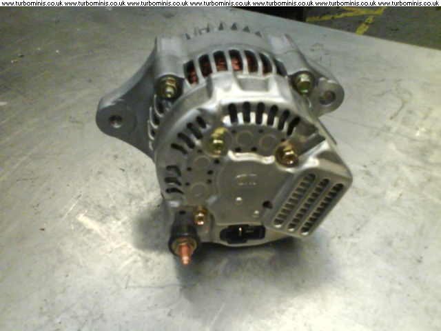
Bottom picture matty
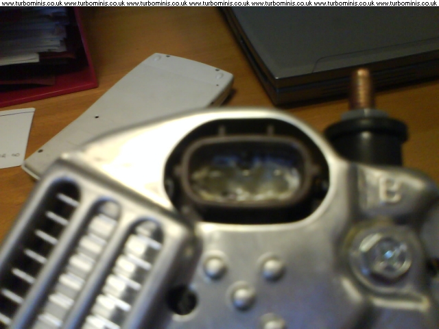
One main post and then 2 spade terminals in a T shape
One main post and then 2 spade terminals in a T shape
#6
matty...
-
- Traders
-
- 605 posts
Super Mini Mad
- Location: Oxfordshire
- Local Club: Turbominis
Posted 16 April 2008 - 01:04 PM
Ive connected mine up so the
brown and yellow wire is on spade nearest the threaded terminal.
Brown wire is on the threaded terminal
Brown and green (I think it was) is also on the threaded terminal
I don't think the other terminal is needed. I tried connecting the brown and yellow to the other spade and the light didn't turn on and it does on the one I suggested above, which suggests that the pin is a grounding, if it gives 12v on start up then the light will go out.
Ive got mine fitted but been too busy with mapping to even look at what the ignition light is doing! Lol
#7
Udo
-
- Members
-
- 1,670 posts
Camshaft & Stage Two Head
- Location: Lincoln
Posted 16 April 2008 - 01:49 PM
Cheers mate i'll try that tonight
#8
Udo
-
- Members
-
- 1,670 posts
Camshaft & Stage Two Head
- Location: Lincoln
Posted 16 April 2008 - 05:10 PM
Ive connected mine up so the
brown and yellow wire is on spade nearest the threaded terminal.
Brown wire is on the threaded terminal
Brown and green (I think it was) is also on the threaded terminal
I don't think the other terminal is needed. I tried connecting the brown and yellow to the other spade and the light didn't turn on and it does on the one I suggested above, which suggests that the pin is a grounding, if it gives 12v on start up then the light will go out.
Ive got mine fitted but been too busy with mapping to even look at what the ignition light is doing! Lol
Nope that don't work either

#9
matty...
-
- Traders
-
- 605 posts
Super Mini Mad
- Location: Oxfordshire
- Local Club: Turbominis
Posted 16 April 2008 - 06:58 PM
Hmmm....get a multimeter and check the continuity between the pins and ground. One of them should read 0.3 Ohms or there abouts? And that should be the one to connect it to.
#10
Udo
-
- Members
-
- 1,670 posts
Camshaft & Stage Two Head
- Location: Lincoln
Posted 16 April 2008 - 07:04 PM
....heads off to garage
right just to check, do I have the battery connected and key in position 2. Do I disconnect the wires? where do I put each probe of the meter
I'm having a real brain ache on this
right just to check, do I have the battery connected and key in position 2. Do I disconnect the wires? where do I put each probe of the meter
I'm having a real brain ache on this
Edited by Udo, 16 April 2008 - 07:13 PM.
#11
matty...
-
- Traders
-
- 605 posts
Super Mini Mad
- Location: Oxfordshire
- Local Club: Turbominis
Posted 16 April 2008 - 07:50 PM
Without any wires going to the alternator spade terminals put one probe on the spade one on the body (grounding point) and do the same for the other spade connection one of them shoul meter out as a short and the other open circuit.
I'll go and check mine aswell...
I'll go and check mine aswell...
#12
Udo
-
- Members
-
- 1,670 posts
Camshaft & Stage Two Head
- Location: Lincoln
Posted 16 April 2008 - 07:53 PM
http://www.turbomini...p...&tid=148646
Think this is what I have done (bangs head against wall as have now cooked the diodes probably)
but then whats the difference between permanent live and one which comes off the ign as they are both 12v?
Think this is what I have done (bangs head against wall as have now cooked the diodes probably)
but then whats the difference between permanent live and one which comes off the ign as they are both 12v?
Edited by Udo, 16 April 2008 - 08:05 PM.
#13
matty...
-
- Traders
-
- 605 posts
Super Mini Mad
- Location: Oxfordshire
- Local Club: Turbominis
Posted 16 April 2008 - 08:20 PM
Right ive checked mine and when the wire is plugged onto the other spade the light doesn't turn on! Ive left my bl00dy meter at work!
Is there voltage between the spades and ground? Is there voltage between the threaded terminal and spades?
I think you'll be alright to be honest as you haven't run the engine and you have only put 12V where it is needed.
Is there voltage between the spades and ground? Is there voltage between the threaded terminal and spades?
I think you'll be alright to be honest as you haven't run the engine and you have only put 12V where it is needed.
Edited by matty..., 16 April 2008 - 08:22 PM.
#14
Udo
-
- Members
-
- 1,670 posts
Camshaft & Stage Two Head
- Location: Lincoln
Posted 16 April 2008 - 08:37 PM
Just tried what I had found in that Turbominis link and still nothing
I still dont understand how if its wired like you said to start with ie brown/yellow to the terminal nearest the post and the brown and brown/blue both to the post why yours works and mine wont
Can you see if the brown/yellow is connected to the L terminal or IG terminal on mine the L terminal is FURTHEST away from the post
Oh and the battery in my meter has decided now is a good time to go flat!
#15
Udo
-
- Members
-
- 1,670 posts
Camshaft & Stage Two Head
- Location: Lincoln
Posted 16 April 2008 - 08:46 PM
Right ive checked mine and when the wire is plugged onto the other spade the light doesn't turn on! Ive left my bl00dy meter at work!
Is there voltage between the spades and ground? Is there voltage between the threaded terminal and spades?
I think you'll be alright to be honest as you haven't run the engine and you have only put 12V where it is needed.
Right found a battery for meter
car battery connected key in off position
between main post and either teminal I get 12.8v
nothing between spades and ground
not geting anywhere near 0.3ohms from your previous post getting just over 4.??ohms (can't remember)


1 user(s) are reading this topic
0 members, 1 guests, 0 anonymous users


