Well i bought a brand new dashboard for my 1983 mini City E, it's a 3 clock CENTRAL SPEEDO DASH originaly mine was just one centre clock. When i tried to fit it i noticed that there is no bracket/s with the dash for the centre clock does anyone know what they look like i've searched the various forums and minispares pages for the last two days but have found nothing.
Thanks Mick


3 Clock Central Speedo Dash (centre Clock Fixings)
Started by
MiniMick
, Apr 17 2008 09:29 PM
8 replies to this topic
#2
: post #2")
cambiker71
-

- Members
-

- 1,050 posts
One Carb Or Two?
- Location: Peterborough, Cambs
- Local Club: Cambscustomclassics.com
Posted 17 April 2008 - 10:02 PM
Isn't it just held in place with the four screws like the single clock one? The one i have here does, undo the four screws holding the original single clock plastic surround to the bulkhead, drop the heater down to make life easier to get at the bottom two, remove single clock set up, fit triple set up, making sure you seal round the mating faces or water will drip on your feet when it rains and engine fumes will get into the car. All that will need doing is adding a feed wire to the temp guage from the voltage stabiliser on the back of the speedo and another wire from the negative terminal down to the sender unit on the cylinder head (once the blanking plug is removed to fit it) the oil pressure guage is mechanical so easy to work out, take the pipe from the oil pressure switch hole or on a 't' piece to have a warning lamp as well as the guage.Well i bought a brand new dashboard for my 1983 mini City E, it's a 3 clock CENTRAL SPEEDO DASH originaly mine was just one centre clock. When i tried to fit it i noticed that there is no bracket/s with the dash for the centre clock does anyone know what they look like i've searched the various forums and minispares pages for the last two days but have found nothing.
Thanks Mick
Hope this is useful
#3
dklawson
-

- TMF+ Member
-
- 10,923 posts
Moved Into The Garage
- Name: Doug
- Location: Durham, NC - USA
- Local Club: none
Posted 18 April 2008 - 02:17 AM
The 3-gauge center binnacles fall into two main categories, Mk1 and everything else.
The Mk1 binnacle is very different and may be what you bought. It starts with the plastic center binnacle for just the speedo. That bolts to the firewall with four screws. There is a metal plate that goes over the front of that. It's an oval metal plate with cutouts for the three gauges. Tabs/ears on the back of that attach to the plastic binnacle. Finally, there is the black, plastic, blow molded oval cover with the chrome trim piece. that attaches with four screws to the oval metal plate.
The later binnacles are a much thicker plastic oval. This is a one-piece assembly. It has four slotted holes on a rear mounting flange the bolts directly to the firewall. The gauges fit directly in holes on the front.
#4
MiniMick
-
- Members
-
- 508 posts
Super Mini Mad
Posted 18 April 2008 - 05:16 PM
Sorry not to have got back sooner, right my original clock is a single centre clock on a plastic shroud.
The shroud is fitted via four screws to the bulk head and the single centre clock is held to the shroud with 2 screws set at 9 O'Clock and 3 O'Clock (if you know what i meen).
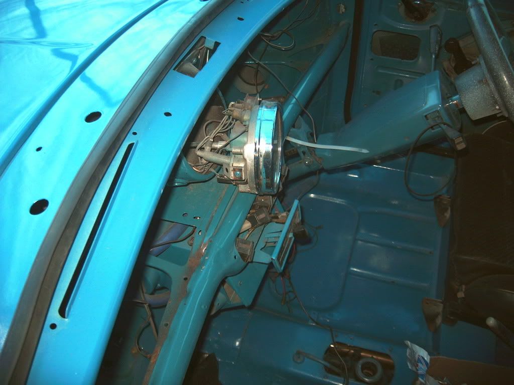
The dash that i'm fitting is a full peice dash (picy included)
I'm guessing that there should be two L shaped brackets to fit to the back of the full peice dash for the 2 clock screws to fit too?
The shroud is fitted via four screws to the bulk head and the single centre clock is held to the shroud with 2 screws set at 9 O'Clock and 3 O'Clock (if you know what i meen).
The dash that i'm fitting is a full peice dash (picy included)
I'm guessing that there should be two L shaped brackets to fit to the back of the full peice dash for the 2 clock screws to fit too?
#5
dklawson
-
- TMF+ Member
-
- 10,923 posts
Moved Into The Garage
- Name: Doug
- Location: Durham, NC - USA
- Local Club: none
Posted 18 April 2008 - 06:27 PM
Thanks for the picture. I thought you were trying to fit an oval center binnacle.
Others will have to post what hardware is needed for what you're fitting. I agree that there should be some form of "L" brackets on the back of the panel you purchased.
Others will have to post what hardware is needed for what you're fitting. I agree that there should be some form of "L" brackets on the back of the panel you purchased.
#6
MiniMick
-
- Members
-
- 508 posts
Super Mini Mad
Posted 18 April 2008 - 08:01 PM
Thanks for the picture. I thought you were trying to fit an oval center binnacle.
Others will have to post what hardware is needed for what you're fitting. I agree that there should be some form of "L" brackets on the back of the panel you purchased.
Yep i gathered that maybe i didn't explain myself properly originaly thats why i added the graph.
Thanks anyway bro
Mick
#7
MiniMick
-
- Members
-
- 508 posts
Super Mini Mad
Posted 20 April 2008 - 09:19 PM
Got a graph of my clock now as well of the dash i'm fitting if this can help people to identify what bit/s i'm looking for
#9
dklawson
-
- TMF+ Member
-
- 10,923 posts
Moved Into The Garage
- Name: Doug
- Location: Durham, NC - USA
- Local Club: none
Posted 21 April 2008 - 07:53 PM
If no one posts with proper pictures or information... you could always make your own "L" brackets and carefully attach them to the back of the dash panel you've got.
I would do this....
Offer the speedo up to the back side of the wooden panel such that the gauge is pushed forward and is horizontal. Make cardboard template "L" pieces (about 1 inch [25mm] wide) and fit them to the side of your gauge. Mark hole locations where the speedo mounting screws need to pass through. Trace the outline of the cardboard "L" on the backside of the wood. Use the templates to make metal "L" brackets, preferably out of aluminum since it's easy to cut and drill. Drill the speedo mounting screws over-sized so you can move the gauge around a bit.
If the wooden panel is thick enough (say more than 5/16" [8mm]) consider using very small, short wood screws to attach the metal "L" brackets to the back side of the wood panel. If you can do this, make small holes through the "L" brackets first then use a marker to transfer the hole locations to the back side of the wood panel. Use a drill stop on the drill bit and drill shallow, blind, pilot holes for the screws that will NOT break through the front side. Use epoxy and short, small wood screws to secure the "L" brackets in place.
If the panel is too thin to safely use small, short wood screws, I would still drill a series (a lot) of small holes through the metal "L" bracket on the surface that will contact the back side of the wood. Roughen that surface of the "L" bracket using sandpaper or a coarse file. Clean the back side of the wooden panel being careful not to remove the bracket template outline you traced in paragraph 2 above. Use epoxy to glue the "L" brackets in place, centering the brackets within the outline traced in paragraph 2. Clamp the bracket in place so it doesn't move while the glue sets.
by the way, I do not like using 5-minute epoxy for anything. I would never use it here. I would look for an epoxy that takes 24 hours to cure. The longer cure epoxies have better moisture and temperature resistance and typically have higher shear strength.
Sorry for the long winded post but no one else was offering you any suggestions. In closing, with any project like this... measure twice and cut once. Always dry fit the pieces before drilling holes and/or applying glue.


1 user(s) are reading this topic
0 members, 1 guests, 0 anonymous users


