Jump to content


Photo
- - - - -

Engine Bay Wiring Queries


  • Please log in to reply
12 replies to this topic

#1 padnic

padnic

    Mini Mad

  • Members
  • PipPipPipPip
  • 271 posts

Posted 30 July 2008 - 08:43 PM

Really need some help with knowing which wires go where........call me stupid but i really am no good at following the haynes manual or wiring diagrams so i'm hoping somebody will be able to help me here.

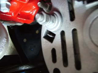
What colour wire with spade connector goes to the alternator?

Posted Image

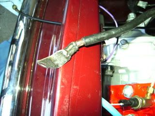
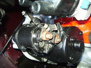
The black battery wire that goes from the boot to the engine bay, i know it goes to the starter motor but to which point?

Posted Image Posted Image

Also i have these wires white and black, white and yellow, pink and white

Then 2 brown eyelets , brown and red wire, white and yellow wire

Posted Image Posted Image

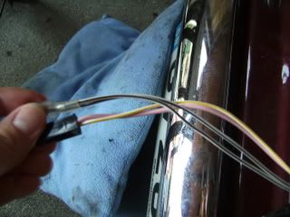
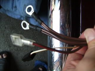
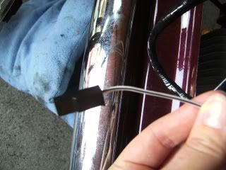
The a white and black on its own:
Posted Image

any help is really appreciated!!
Thanks

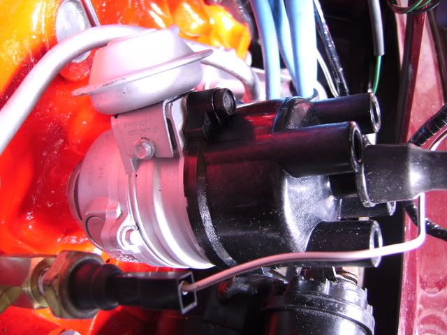
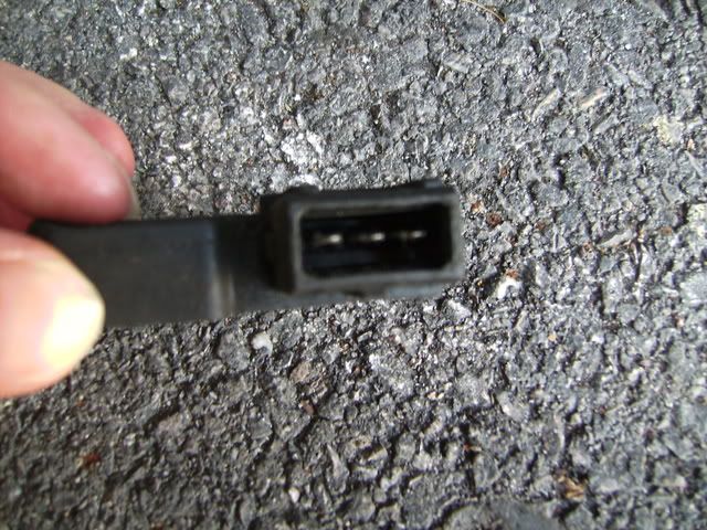
Sorry forgot to add that some of these wires go to the ignition module (which has 3 small pins) and some go to the coil

Edited by padnic, 30 July 2008 - 08:45 PM.


#2 coopersmate

coopersmate

    Speeding Along Now

  • Members
  • PipPipPipPipPip
  • 408 posts

Posted 30 July 2008 - 09:17 PM

Is this a brand new loom?
What year and model is the loom for or the car is?

#3 insamoufonyx

insamoufonyx

    Camshaft & Stage Two Head

  • Members
  • PipPipPipPipPipPipPipPip
  • 1,633 posts
  • Local Club: NorthSomersetMiniClub.co.uk

Posted 30 July 2008 - 09:48 PM

looks like a brand new loom to me, very nice! the one in the last picture goes between the taco and somewhere, but i cant rember the other end will look it up for you

#4 Dan

Dan

    On Sabbatical

  • TMF+ Member
  • PipPipPipPipPipPipPipPipPipPipPip
  • 21,354 posts

Posted 30 July 2008 - 10:01 PM

Nothing connects to the spade on the alternator. The alternator only connects by the large three terminal plug. Insulate the large stud on the back of the alternator with self amalgamating tape, this is an output for cars with different wiring and it will be a disaster if anything grounds it.

The main battery feed goes to the large stud on the solenoid.

The pink/white and white/yellow spliced together are the coil supply.

The double white/black is the coil ground.

2 double brown eyelets go to the same terminal on the solenoid as the battery feed.

Brown/red to the solenoid trigger spade.

Single white/yellow to the solenoid cranking bypass spade.

Single white/black to the LT wire coming out of the dizzy body.

That is all as standard though, you say you have a module on the dizzy so I assume it's electronic ignition. What type is it? Got a photo? This will change some things.

#5 padnic

padnic

    Mini Mad

  • Members
  • PipPipPipPip
  • 271 posts

Posted 31 July 2008 - 03:47 PM

Is this a brand new loom?
What year and model is the loom for or the car is?


yeah its a brand new loom, its a 1989 mini 30

#6 padnic

padnic

    Mini Mad

  • Members
  • PipPipPipPip
  • 271 posts

Posted 31 July 2008 - 03:50 PM

Nothing connects to the spade on the alternator. The alternator only connects by the large three terminal plug. Insulate the large stud on the back of the alternator with self amalgamating tape, this is an output for cars with different wiring and it will be a disaster if anything grounds it.

The main battery feed goes to the large stud on the solenoid.

The pink/white and white/yellow spliced together are the coil supply.

The double white/black is the coil ground.

2 double brown eyelets go to the same terminal on the solenoid as the battery feed.

Brown/red to the solenoid trigger spade.

Single white/yellow to the solenoid cranking bypass spade.

Single white/black to the LT wire coming out of the dizzy body.

That is all as standard though, you say you have a module on the dizzy so I assume it's electronic ignition. What type is it? Got a photo? This will change some things.


Thanks for your help Dan. Yeah its electronic ignition, code 42664A / AUU1536 i've took a picture of it and also one of the pins on the module
Thanks

Posted Image

Posted Image

#7 Dan

Dan

    On Sabbatical

  • TMF+ Member
  • PipPipPipPipPipPipPipPipPipPipPip
  • 21,354 posts

Posted 31 July 2008 - 11:23 PM

Firstly if your 30 has still got its 998 engine in then that dizzy is not going to be your friend unless you've had it adjusted.

The bad news is that this dizzy needs a specific electronic type coil that needs a 12 volt supply rather than the ballasted supply your new loom provides. You can easily add a new circuit though, and hide the original. Make sure you have the right coil for one thing. Then take the paired pink/white and white/yellow cable at the coil connection, insulate the end well with tape and tape it back along the loom. You can tape it all down and hide it to make it look original. Do the same with the other end of the white/yellow cable at the solenoid. Now you need to create a new ignition supply and since it's electronic I prefer to do this using a fused circuit. Get some (preferably white) cable rated to at least 10 amps and connect in to the unfused side of fuse #1 in your fuse box. Fit an inline fuse in the circuit to give protection at about 8 amps (that'll be labelled 15 amps if it's a glass cartridge or 7.5 amps and brown in colour if you use a blade, a 10 amp blade is easier to find and would be fine). I'll give you a link later to somewhere you can buy parts including in-line fuse holders that will all look original. Keep the fuse up somewhere near the fuse box. Make sure it's on the unfused side of the fusbox on fuse #1 (your meter or lamp will still show power at the terminal with the ignition on and the fuse removed it you have the right one) because having two fuses in a circuit is a no-no. Now run the wire down the wing along the new harnes. Tape it in if you like (use non-adhesive loom tape) or just tie wrap it to the outside. This is the new coil feed and runs to the coil positive. The paired white/black cables are still the coil negative but find the other end of the original dizzy LT connection (the single white/black) and again insulate the end and tape it back to the loom out of the way. Now you need to go to somewhere like Mini Spares and get the short jumper loom that connects your dizzy module to the coil, and to your new circuit. That should be all you need to do. You can make the little jumper cable if you like but tracking down the right plug is not easy as many of these different 'timer housing' plugs look similar but aren't compatible.

Autosparks have all the parts you need to make your new circuit look like it is original equipment, including the proper posi-lock connectors and their black insulators for the coil just like you have now and proper in-line fuse holders.

#8 padnic

padnic

    Mini Mad

  • Members
  • PipPipPipPip
  • 271 posts

Posted 01 August 2008 - 07:43 AM

Firstly if your 30 has still got its 998 engine in then that dizzy is not going to be your friend unless you've had it adjusted.

The bad news is that this dizzy needs a specific electronic type coil that needs a 12 volt supply rather than the ballasted supply your new loom provides. You can easily add a new circuit though, and hide the original. Make sure you have the right coil for one thing. Then take the paired pink/white and white/yellow cable at the coil connection, insulate the end well with tape and tape it back along the loom. You can tape it all down and hide it to make it look original. Do the same with the other end of the white/yellow cable at the solenoid. Now you need to create a new ignition supply and since it's electronic I prefer to do this using a fused circuit. Get some (preferably white) cable rated to at least 10 amps and connect in to the unfused side of fuse #1 in your fuse box. Fit an inline fuse in the circuit to give protection at about 8 amps (that'll be labelled 15 amps if it's a glass cartridge or 7.5 amps and brown in colour if you use a blade, a 10 amp blade is easier to find and would be fine). I'll give you a link later to somewhere you can buy parts including in-line fuse holders that will all look original. Keep the fuse up somewhere near the fuse box. Make sure it's on the unfused side of the fusbox on fuse #1 (your meter or lamp will still show power at the terminal with the ignition on and the fuse removed it you have the right one) because having two fuses in a circuit is a no-no. Now run the wire down the wing along the new harnes. Tape it in if you like (use non-adhesive loom tape) or just tie wrap it to the outside. This is the new coil feed and runs to the coil positive. The paired white/black cables are still the coil negative but find the other end of the original dizzy LT connection (the single white/black) and again insulate the end and tape it back to the loom out of the way. Now you need to go to somewhere like Mini Spares and get the short jumper loom that connects your dizzy module to the coil, and to your new circuit. That should be all you need to do. You can make the little jumper cable if you like but tracking down the right plug is not easy as many of these different 'timer housing' plugs look similar but aren't compatible.

Autosparks have all the parts you need to make your new circuit look like it is original equipment, including the proper posi-lock connectors and their black insulators for the coil just like you have now and proper in-line fuse holders.


Cheers Dan, Its a 1275 metro engine in my mini does this change alot?

#9 padnic

padnic

    Mini Mad

  • Members
  • PipPipPipPip
  • 271 posts

Posted 02 August 2008 - 03:35 PM

Dan?? Anybody??

#10 Dan

Dan

    On Sabbatical

  • TMF+ Member
  • PipPipPipPipPipPipPipPipPipPipPip
  • 21,354 posts

Posted 02 August 2008 - 08:00 PM

Nope, changes nothing (except that the dizzy will work with the engine better than it would with the 998).

#11 padnic

padnic

    Mini Mad

  • Members
  • PipPipPipPip
  • 271 posts

Posted 02 August 2008 - 08:50 PM

Nope, changes nothing (except that the dizzy will work with the engine better than it would with the 998).


Thanks alot for your help

#12 Dan

Dan

    On Sabbatical

  • TMF+ Member
  • PipPipPipPipPipPipPipPipPipPipPip
  • 21,354 posts

Posted 03 August 2008 - 04:37 PM

As per my PM.

Edited by Dan, 03 August 2008 - 04:39 PM.


#13 padnic

padnic

    Mini Mad

  • Members
  • PipPipPipPip
  • 271 posts

Posted 03 August 2008 - 05:55 PM

As per my PM.


Thanks Dan, i'll go sort it now.


1 user(s) are reading this topic

0 members, 1 guests, 0 anonymous users