

Just Can't Find The Problem!
Started by
Roo
, Jan 27 2009 08:06 PM
72 replies to this topic
#16

WiredbyWilson
-
- Traders
-

- 5,004 posts
WiredByWilson
- Location: Kent
- Local Club: WiredByWilson
Posted 28 January 2009 - 09:46 PM
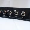
This is the fuse box i *think* the haynes is referring too - judging by the shortness of the feed I would say it is pretty close to the starter.
#17
nicksuth
-

- Noobies
-
- 1,631 posts
Camshaft & Stage Two Head
- Location: Lutterworth
- Local Club: Rugby Classic Mini Owners Club
Posted 28 January 2009 - 10:06 PM
I thought that was only fitted to the MPi Minis (known as fused links or link fuses or something like that)???
#18
WiredbyWilson
-
- Traders
-
- 5,004 posts
WiredByWilson
- Location: Kent
- Local Club: WiredByWilson
Posted 28 January 2009 - 10:09 PM
Ah that is what the Haynes is referring to - so it seemd my haynes is pap then as only does pre or post oct 1996 wiring 
#19
WiredbyWilson
-
- Traders
-
- 5,004 posts
WiredByWilson
- Location: Kent
- Local Club: WiredByWilson
Posted 28 January 2009 - 11:08 PM
Right just spent an hour reading the Haynes 
This is what i found-
Battery connects to:
ECU via fused link
Alternator
Starter Motor
Ignition
Other (for now bear with me)
We can ignore the link to ECU/Alt/Starter for now.
Ignition connects to-
AUX position: Radio via radio fuse & Clocks/Fan via Fuse 5/6 [light green/white wire]
IGN position: Lights indicators via fuse 1/2 & ECU Clocks via line fuse (7) [white wire]
CRANK position: ECU [white/red wire]
Other connects to- (seems to be a mutil loom connection) [brown wires]
Lighting
Cooling fan via line fuse (5) [purple wire]
Brake Test Switch via line fuse (3) [brown/orange wire]
Brake Test/Lighting/Radio via fuse 3/4 [purple wire]
Indicators/Interior Light via line fuse (1) [pink/orange wire]
Line fuses can be found on Bulkhead, Behind Facia or on slam panel under bonnet lock (in your case roo it may be a good place to start as i assume yours are no longer located here.
The more I think about it the ignition switch may be duff too......
Hope that is of some help.
Edited by Wilson1275, 28 January 2009 - 11:12 PM.
#20
minicooper1.3i
-

- Members
-
- 871 posts
One Carb Or Two?
- Location: Bedford
- Local Club: na
Posted 29 January 2009 - 03:07 PM
Hey Roo!
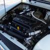
As you've checked your supplies and fuses and they seem ok, have you checked your earths yet? Even if you've got 12V to your starter motor, it won't work if the earth strap from the top engine steady to bulkhead isn't working. Assuming the earths on the SPi are same / similar to an MPi, you should have one from the engine steady to the bulkhead and one from the ecu loom to the angle brace in front of the offside tower bolt in the engine bay. Srocket can confirm if that's correct for a late SPi.
Hope you get it sorted soon!
Good luck!
#21
Sprocket
-
- Members
-
- 7,266 posts
Great on Injection faults
- Location: Warrington
- Local Club: Manchester Minis
Posted 29 January 2009 - 06:12 PM
Right just spent an hour reading the Haynes
This is what i found-
Battery connects to:
ECU via fused link
Alternator
Starter Motor
Ignition
Other (for now bear with me)
We can ignore the link to ECU/Alt/Starter for now.
Ignition connects to-
AUX position: Radio via radio fuse & Clocks/Fan via Fuse 5/6 [light green/white wire]
IGN position: Lights indicators via fuse 1/2 & ECU Clocks via line fuse (7) [white wire]
CRANK position: ECU [white/red wire]
Other connects to- (seems to be a mutil loom connection) [brown wires]
Lighting
Cooling fan via line fuse (5) [purple wire]
Brake Test Switch via line fuse (3) [brown/orange wire]
Brake Test/Lighting/Radio via fuse 3/4 [purple wire]
Indicators/Interior Light via line fuse (1) [pink/orange wire]
Line fuses can be found on Bulkhead, Behind Facia or on slam panel under bonnet lock (in your case roo it may be a good place to start as i assume yours are no longer located here.
The more I think about it the ignition switch may be duff too......
Hope that is of some help.
There is no wiring diagram for the SPi with the 24way fuse box and if there is I have not yet found it. What you have to do is use the old SPi wiring diagram for the main part of the loom, they are layed out much the same, little changed, and then just accept the fact that all the fuses are now in the one place and blade type. The haynes manual does describe the 24 way fuse box and the circuits it serves, which is all you really need. Just ignore all the refferences to fusing in the diagrams.
There are no other fuses on the 24way fuse boxed SPi loom, I know this for a fact as I have had the entire loom out of the car when I re built it. There is the 24 way fuse box and the Hypalon Fuse links in the loom itself at the point where they join to the starter motor battery terminal.
#22
WiredbyWilson
-
- Traders
-
- 5,004 posts
WiredByWilson
- Location: Kent
- Local Club: WiredByWilson
Posted 29 January 2009 - 07:24 PM
Well i stand corrected sprocket, and have been told by roo that you have mentioned this previously so I apologise. I was only reading the haynes as assumed it would be somewhere near right! What is the point in Haynes producing wiring diagrams that aren't right then?
So now I would just like to say that i have no idea what is wrong with Phoenix - but maybe somewhere in the loom it has broken or melted and mangled itself together.
So now I would just like to say that i have no idea what is wrong with Phoenix - but maybe somewhere in the loom it has broken or melted and mangled itself together.
Edited by Wilson1275, 29 January 2009 - 07:31 PM.
#23
taffy1967
-

- Members
-
- 9,896 posts
Whovian
- Local Club: South Wales Minis
Posted 29 January 2009 - 07:27 PM
I don't know if this is of any help, but it's the fuse box ratings as fitted to the last of the SPi Minis: -
(1996) 24 Fuse Engine Bay Fuse box: -
1 -- 15a -- Rear screen heater
2 -- 15a -- Reversing lamps, stop lamps, headlamp dim-dip, indicator relay
3 -- 15a -- Auxiliary cooling fan
4 -- 15a -- Headlamp dim-dip
5 -- 15a -- Heater blower, sunroof where fitted
6 -- 15a -- Wash / wipe
7 -- 20a -- Headlamp flasher, horn, alarm
8 -- 10a -- Tacho, ECU, fuel pump relay, alarm
9 -- 10a -- Stereo, cooling fan relay, auto gear selector lamp
10 -- 10a -- Stereo memory, interior lamp, indicators, hazards, alarm, brake fluid warning
11 -- 10a -- Fuel pump
12 -- 10a -- Starter relay
13 -- 10a -- Side and tail lamps left hand, number plate lamp
14 -- 10a -- Side and tail lamps right hand, instrument lamps
15 -- 10a -- Main beam headlamp left hand
16 -- 10a -- Main beam headlamp right hand & warning lamp
17 -- 10a -- Dip beam headlamp left hand
18 -- 10a -- Dip beam headlamp right hand
19 -- 20a --}
20 -- 15a --}These fuses reserved for overseas spec systems
21 -- 10a --}and accessories (A/C system, front fog lamps etc.)
22 -- 20a --}
23 -- N/C
24 -- 10a -- Rear fog lamp
#24
WiredbyWilson
-
- Traders
-
- 5,004 posts
WiredByWilson
- Location: Kent
- Local Club: WiredByWilson
Posted 29 January 2009 - 07:32 PM
Roo said she has checked all the fuses and they are all ok.
Does anyone know where the loom gets its power - im guessing it is connected to the satrter motor like most minis?
Does anyone know where the loom gets its power - im guessing it is connected to the satrter motor like most minis?
#25
Roo
-
- TMF+ Member
-
- 3,656 posts
The Queen Of The Curly Wurly
- Local Club: South Central Mini Club!
Posted 29 January 2009 - 09:00 PM
Right i finally got round to doing thise...
I have no power to the systems..... the red line indicates where i feel there is a problem and how the independantly run systems recieve their power (straight off the battery) If i have no power to all the systems and all the fuses are fine there must be a brake some where along that red line.
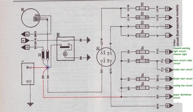
A goes to power distribution circuit
R goes tp Auxiliary cooling fab circuit
Q goes tp Brake test unit
P goes to Brake test unit
O goes to Dim-dip lighting and horn circuit and Radio circuit
N goes to Direction indicator and hazard circuit and interior light circuit
The alarm/immobilisr will run off this power feed somwhere too.
I have no power to the systems..... the red line indicates where i feel there is a problem and how the independantly run systems recieve their power (straight off the battery) If i have no power to all the systems and all the fuses are fine there must be a brake some where along that red line.
A goes to power distribution circuit
R goes tp Auxiliary cooling fab circuit
Q goes tp Brake test unit
P goes to Brake test unit
O goes to Dim-dip lighting and horn circuit and Radio circuit
N goes to Direction indicator and hazard circuit and interior light circuit
The alarm/immobilisr will run off this power feed somwhere too.
#26
WiredbyWilson
-
- Traders
-
- 5,004 posts
WiredByWilson
- Location: Kent
- Local Club: WiredByWilson
Posted 29 January 2009 - 09:17 PM
I would guess it is one of the wires coming off of the battery. So think you will have to start there and trace them hun, would guess one would goto fuse box etc etc.

#27
Sprocket
-
- Members
-
- 7,266 posts
Great on Injection faults
- Location: Warrington
- Local Club: Manchester Minis
Posted 30 January 2009 - 12:25 AM
Right i finally got round to doing thise...
I have no power to the systems..... the red line indicates where i feel there is a problem and how the independantly run systems recieve their power (straight off the battery) If i have no power to all the systems and all the fuses are fine there must be a brake some where along that red line.
A goes to power distribution circuit
R goes tp Auxiliary cooling fab circuit
Q goes tp Brake test unit
P goes to Brake test unit
O goes to Dim-dip lighting and horn circuit and Radio circuit
N goes to Direction indicator and hazard circuit and interior light circuit
The alarm/immobilisr will run off this power feed somwhere too.
Again, that drawing is not quite right
There are Hypalon Fuse links in that part of the circuit. Infact, if i remember correctly there are three. And there are two on the alternator circuit on the engine loom.
It should be fairly easy to check these. The Hypalon is a high strength synthetic rubber. When the fuse link blows it does so with such force, its like an explosion. The Hypalon contains this. What this leaves is the outer sheath. If the fuse link can stretch with light force at any point along its length, it has blown.
The links are primaraly there to prevent a fire in the event of a front impact that could damage the wiring, shorting out and blowing these fuse links.
#28
Roo
-
- TMF+ Member
-
- 3,656 posts
The Queen Of The Curly Wurly
- Local Club: South Central Mini Club!
Posted 31 January 2009 - 10:22 AM
Are you saying Haynes is wrong?
I don't want the fusable links to the alternator cause i have power to that. In the diagram the fused links are labled 32. Alternator is labled 39
I want the wire in the opposite direction to it that has no fusable links... does this go to the black relay box? i have power going into it but cannot test if its going out.
I have no power to the live fuses.
its been over a week now aand i still can't find the problem!!
Edited by Roo, 31 January 2009 - 10:29 AM.
#29
WiredbyWilson
-
- Traders
-
- 5,004 posts
WiredByWilson
- Location: Kent
- Local Club: WiredByWilson
Posted 31 January 2009 - 10:53 AM
I think you are going to have to start pulling the loom apart and find the live feeds and following them through.
But it may be that the live to the alternator is ok but it has no live coming back out of it? Just guessing here really. The haynes isn't clear as to how that spurring point works/where it so you can try and follow it, but i would strt at the starter motor and follow the lives to there respective "homes" from there.
That probably makes no sense - sorry
#30
Roo
-
- TMF+ Member
-
- 3,656 posts
The Queen Of The Curly Wurly
- Local Club: South Central Mini Club!
Posted 31 January 2009 - 10:53 AM
okay tested fuses with ignitio off and on
ignition off fuses that are live are:
headlamps
Ignition on fuses that are live are:
headlamps - including fuses for main an dip beam
Heated rear window
tail lights, reversing light
heater blower
Ecu (engine management)
The only fuses that don't have power are to the systems that don't work.
I have power to alternator, starter, relay box and coil (with ignition on)


0 user(s) are reading this topic
0 members, 0 guests, 0 anonymous users


