Jump to content


Photo

How To Fix Your Nippon S' Temp And Fuel Gauge


  • Please log in to reply
23 replies to this topic

#1 stormintrooper

stormintrooper

    Up Into Fourth

  • Members
  • PipPipPipPipPipPipPipPipPip
  • 2,072 posts

Posted 20 January 2010 - 06:35 PM

Before i go on any further i would like to say a big thanks to DKLawson for the inspiration to do this

First task, a simple one, remove the clear plastic and the inner black face of the cluster so you left with this

Posted Image

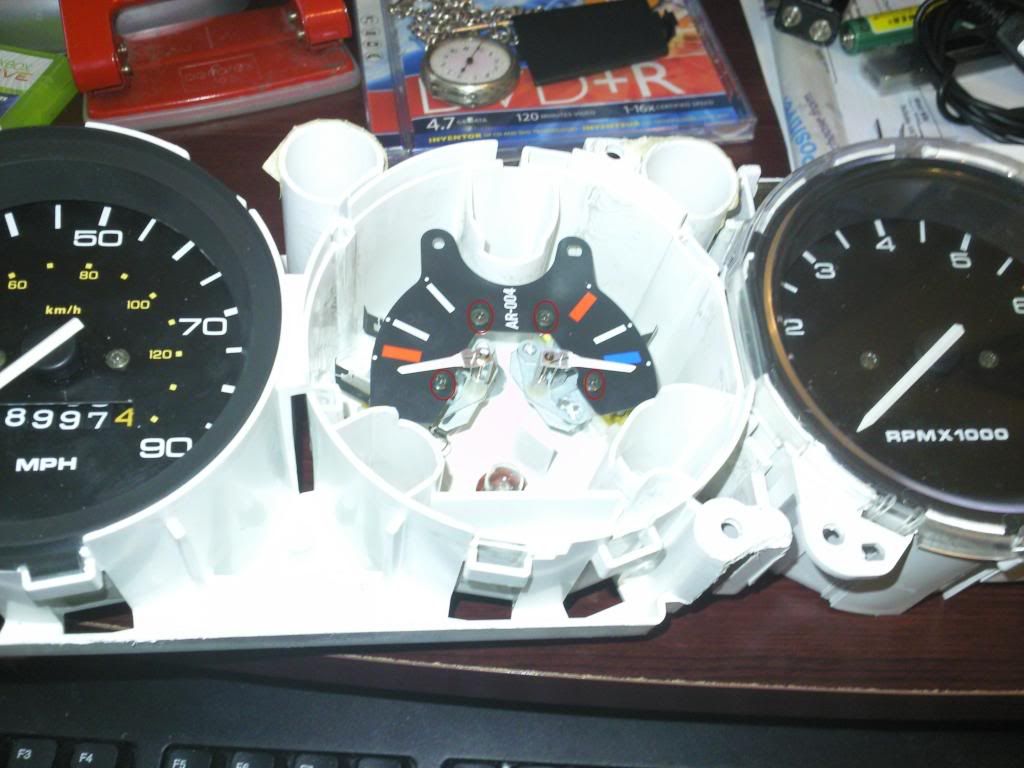
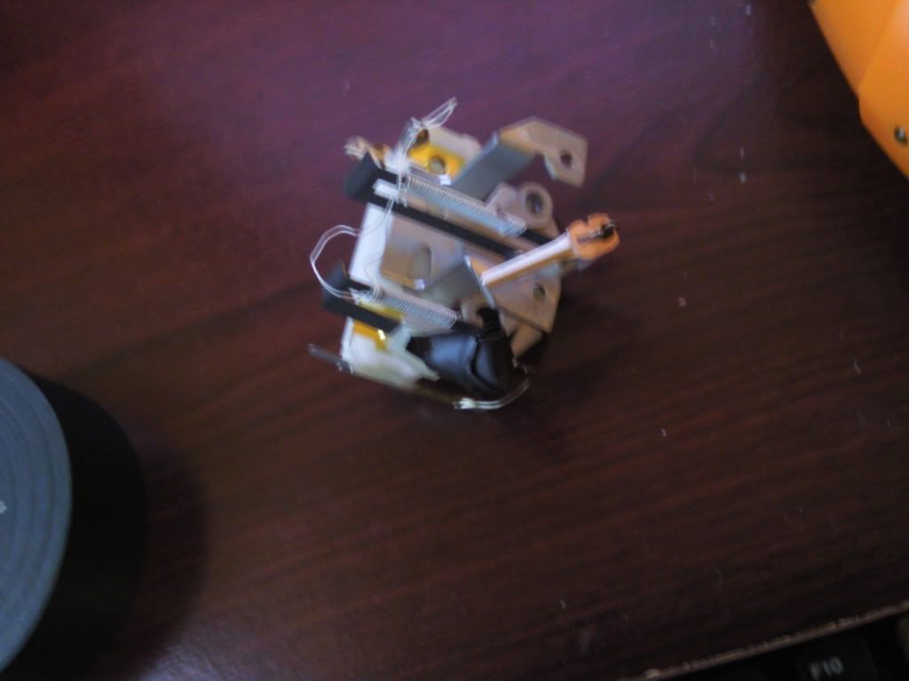
To make things a little easier and to avoid damage to the temp gauge, remove the 4 screws that i have circled red, this allows you to remove the fuel gauge which also holds the voltage stabiliser.

Then flip the cluster round, and remove screws 1 and 4, now this was a picture taken a few steps later hence why 3 screws are already gone.
Posted Image

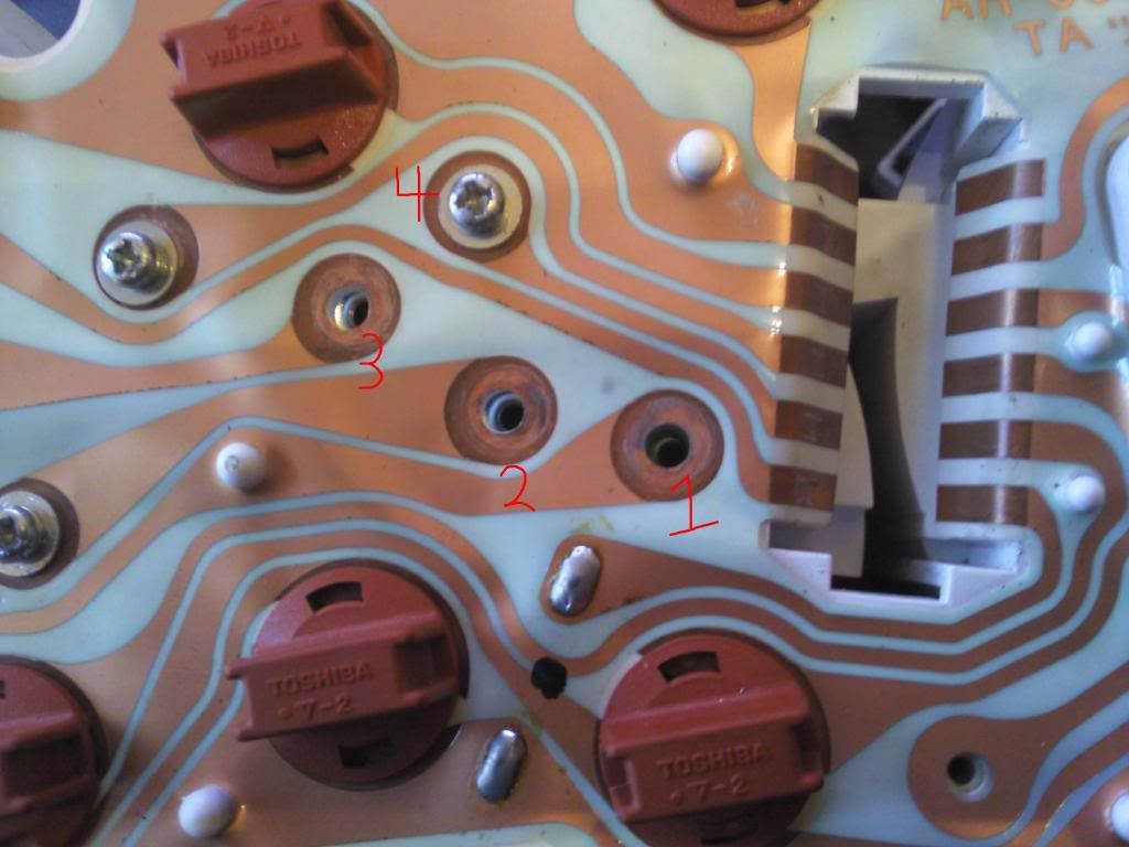
with the gauge removed, you then need to block the contact points marked, i used some electrical tape
Posted Image

Posted Image

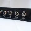
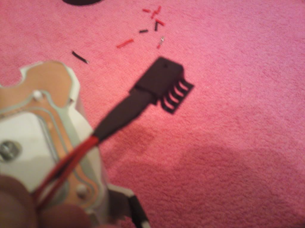
Now...i chose a 1 Amp fixed voltage regulator from maplins

Now before anyone moans..i only had 2 colours of wire so i numbered the pins, 1 is the input, 2 is the ground and 3 is the output
Posted Image

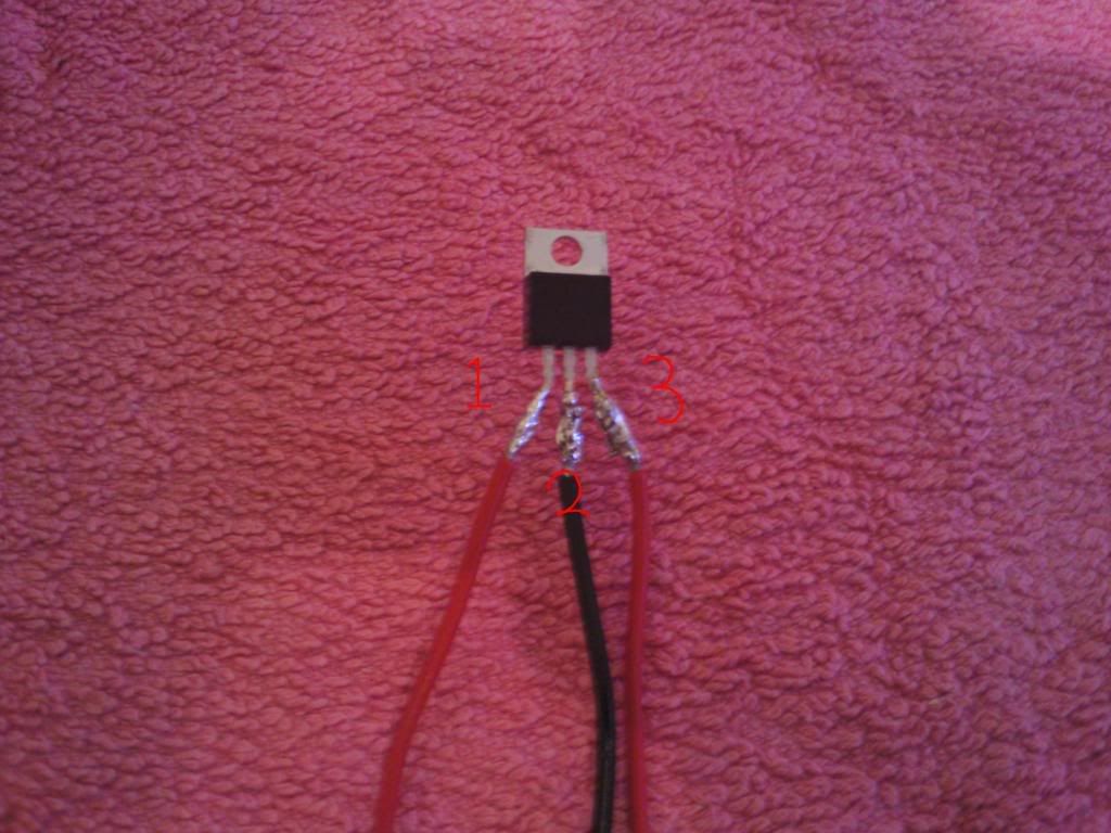
Because of the proximity of each pin, and the fact im not realy any good at soldering :dozing: i used some electrical tape to isolate each terminal, and them wrapped all 3 together for neatness and to ensure they don't move/flex too much

Posted Image

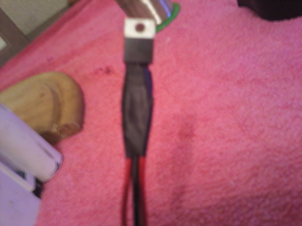
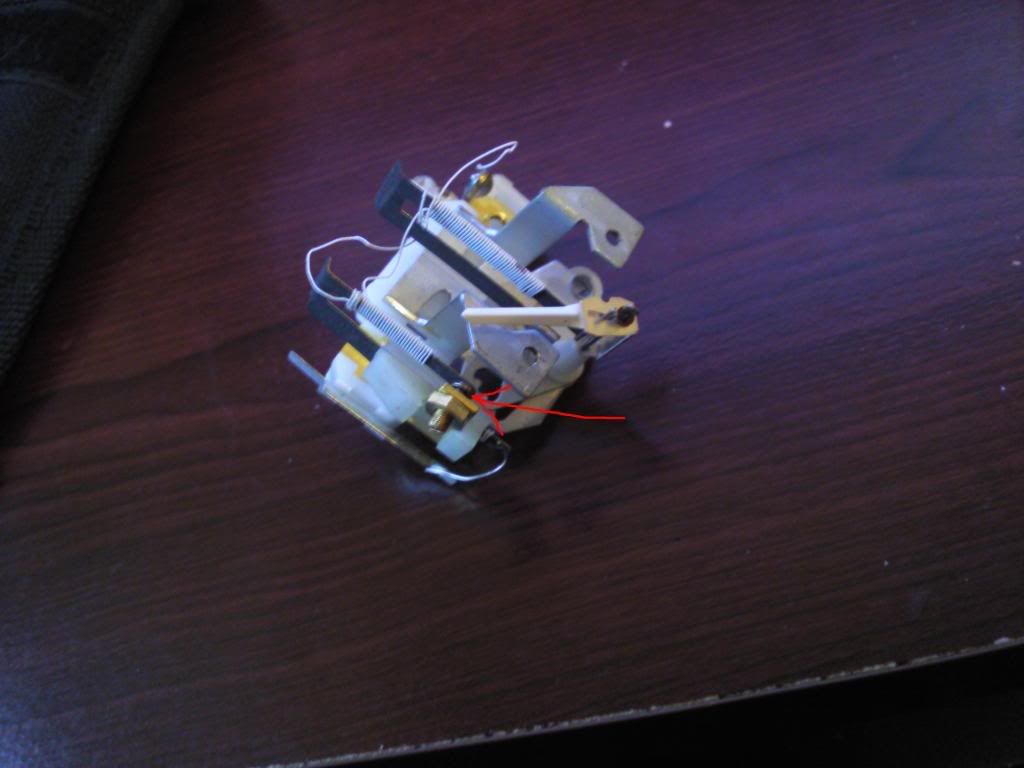
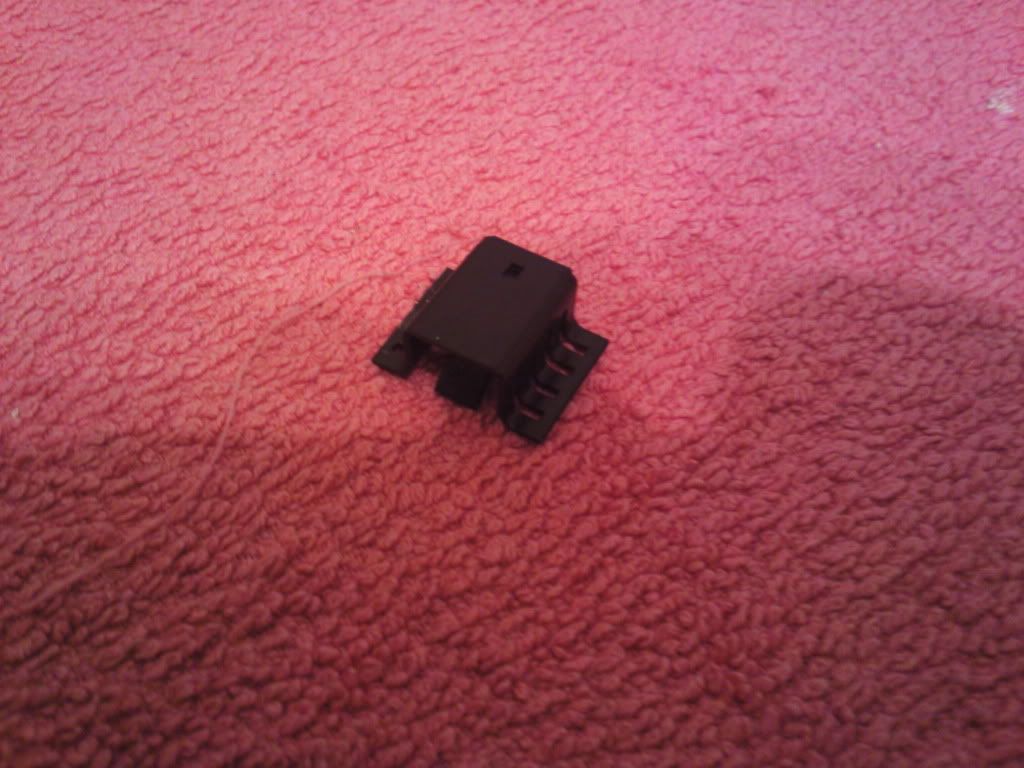
All you have to do now is add some ring terminals to the end of the wires, now its up to you where you mount it, DKLawson suggested moutning it onto the firewall to use it as a heat sink, but personally i didnt fancy having long wires reaching to the bulkhead, so i chose to buy a heatsink for my chip at maplins

Posted Image
Posted Image

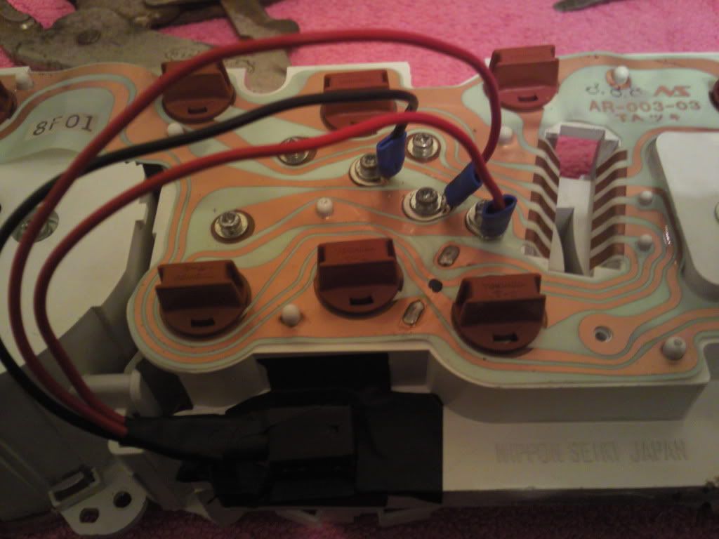
The ring terminals get screwed to the back of the cluster, 1 is the input, 2 is the output and 3 is the ground
Posted Image

with all screws back in you should have a working pair of gauges running at a constant 10V with a deviation of +-0.05V
which is a hell of alot better than the smiths stabiliser going from approx 13.8V to 0V and back again

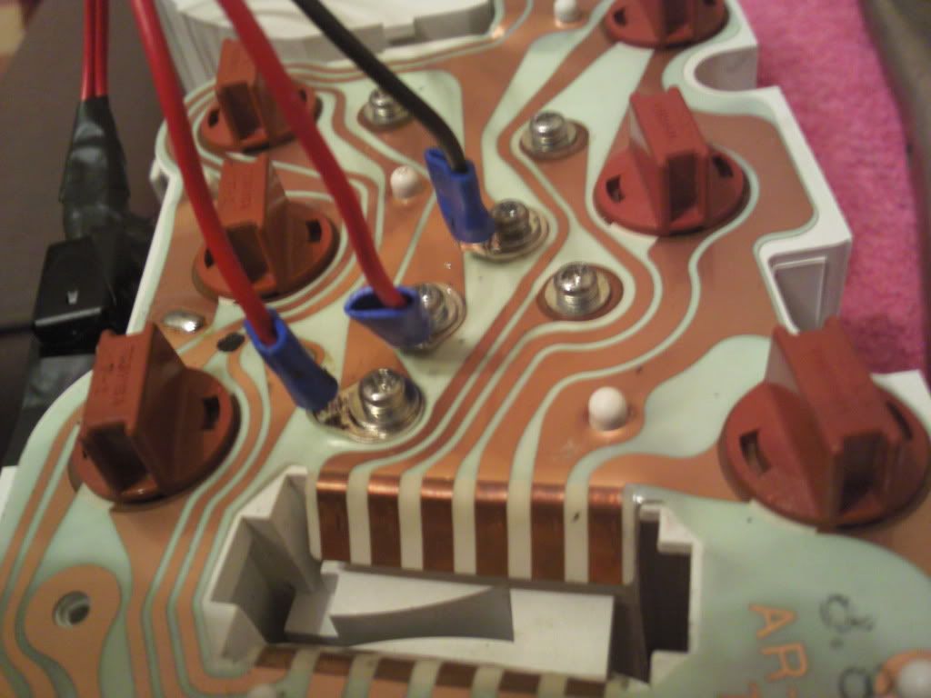
Now i mounted the chip with heatsink to the back of the cluster, please note i have used electrical tape as i misplaced my glue gun which i would have used if i hadnt of lost it, this is only a temporary fixing to stop it from flapping around

Also note i found it neccessary to bend the ring terminals as shown in the pictures, this i found to be neccessary or else the terminals would have came into contact with other PCB lines

Posted Image

Posted Image

the chip and heatsink only cost me just shy of £2 together so this is not an expensive modification, i cannot comment on price of soldering iron, solder, wire and terminals as i have already had them and for some time so unfortunately cannot remember prices

the specific chip i used was maplins order code N38CA

If a MOD would be kind enough to make this a stuck thread or whatever the word is would they please do so as i have seen many to[pictures/threads now on gauges not reading right even though the senders are fine or new.

So this would be a help to many people i am sure

Big thanks to those who helped me with this

Edited by stormintrooper, 20 January 2010 - 06:38 PM.


#2 Guess-Works.com

Guess-Works.com

    Gearbox Guru

  • Traders
  • PipPipPipPipPipPipPipPipPipPipPip
  • 19,838 posts
  • Local Club: Rugby Classic Mini Owners Club

Posted 20 January 2010 - 06:40 PM

Plonk the above into an FAQ, best place for it

PS... Nice find on the chip, been looking for one, well when I think about it I have, but could not find the right spec, but that's spot on.

#3 stormintrooper

stormintrooper

    Up Into Fourth

  • Members
  • PipPipPipPipPipPipPipPipPip
  • 2,072 posts

Posted 20 January 2010 - 06:41 PM

Yh i just realised i put it in the wrong place...silly me :dozing:

#4 WiredbyWilson

WiredbyWilson

    WiredByWilson

  • Traders
  • PipPipPipPipPipPipPipPipPipPip
  • 5,004 posts
  • Location: Kent
  • Local Club: WiredByWilson

Posted 20 January 2010 - 06:46 PM

my gauge doesn't read very accuratly either - does this give better fuel readings?

#5 stormintrooper

stormintrooper

    Up Into Fourth

  • Members
  • PipPipPipPipPipPipPipPipPip
  • 2,072 posts

Posted 20 January 2010 - 06:48 PM

Provided your sender is in full working order then in theory it should give ACCURATE readings

Guess works...i tried putting it into the FAQ's but aparently i dont have permission :dozing:

#6 WiredbyWilson

WiredbyWilson

    WiredByWilson

  • Traders
  • PipPipPipPipPipPipPipPipPipPip
  • 5,004 posts
  • Location: Kent
  • Local Club: WiredByWilson

Posted 20 January 2010 - 06:50 PM

Provided your sender is in full working order then in theory it should give ACCURATE readings

Guess works...i tried putting it into the FAQ's but aparently i dont have permission :dozing:


my sender was brand new when i rebuilt the car - only covered 2000 miles since!

but i know there is around 2 gallons in there and it is at the bottom of the red on the gauge. When i fill it right up it sits between 3/4 and full. :dozing:

#7 stormintrooper

stormintrooper

    Up Into Fourth

  • Members
  • PipPipPipPipPipPipPipPipPip
  • 2,072 posts

Posted 20 January 2010 - 06:50 PM

Well if you want to rule out a gauge problem have a crack at my thread :dozing:

#8 WiredbyWilson

WiredbyWilson

    WiredByWilson

  • Traders
  • PipPipPipPipPipPipPipPipPipPip
  • 5,004 posts
  • Location: Kent
  • Local Club: WiredByWilson

Posted 20 January 2010 - 06:52 PM

Well if you want to rule out a gauge problem have a crack at my thread :dozing:


did you buy the parts instore or online?

#9 stormintrooper

stormintrooper

    Up Into Fourth

  • Members
  • PipPipPipPipPipPipPipPipPip
  • 2,072 posts

Posted 20 January 2010 - 06:54 PM

Instore..i have one local ish to me...within walking distance.....and i had already reseached the chip online so knew what i wanted

#10 yeti21586

yeti21586

    He's A Lumberjack And He's OK

  • TMF+ Member
  • PipPipPipPipPipPipPipPipPip
  • 3,714 posts
  • Name: Chris
  • Location: Hampshire
  • Local Club: None

Posted 20 January 2010 - 06:54 PM

im a bit confused to what it is that , that does.

#11 Guess-Works.com

Guess-Works.com

    Gearbox Guru

  • Traders
  • PipPipPipPipPipPipPipPipPipPipPip
  • 19,838 posts
  • Local Club: Rugby Classic Mini Owners Club

Posted 20 January 2010 - 06:58 PM

tada....

http://www.theminifo...howtopic=146533

#12 stormintrooper

stormintrooper

    Up Into Fourth

  • Members
  • PipPipPipPipPipPipPipPipPip
  • 2,072 posts

Posted 20 January 2010 - 06:59 PM

the chip replaces the voltage regulator that is built into the fuel/temp gauges

giving a more ture 10V all the time

my smiths style regulator had packed up so this was the only option which has turned out to work beautifully

#13 stormintrooper

stormintrooper

    Up Into Fourth

  • Members
  • PipPipPipPipPipPipPipPipPip
  • 2,072 posts

Posted 20 January 2010 - 07:01 PM

Thanks guess works :dozing:

feels good to contribute something to all the members as i know alot of people have problems with theirs and nobody has realy given a definete work around yet, as far as im aware anyway :dozing:

#14 Guess-Works.com

Guess-Works.com

    Gearbox Guru

  • Traders
  • PipPipPipPipPipPipPipPipPipPipPip
  • 19,838 posts
  • Local Club: Rugby Classic Mini Owners Club

Posted 20 January 2010 - 07:01 PM

im a bit confused to what it is that , that does.


It's a voltage regulator, as you may know the voltage of the mini's electrical system can fluctuate between 12v and 14v, for a gauge of this nature it needs a regulated or stabilised voltage, in this case 10v, otherwise as the voltage of your system goes up and down so would the temp and fuel gauge.

#15 taffy1967

taffy1967

    Whovian

  • Members
  • PipPipPipPipPipPipPipPipPipPip
  • 9,896 posts
  • Local Club: South Wales Minis

Posted 20 January 2010 - 07:43 PM

im a bit confused to what it is that , that does.


It's a voltage regulator, as you may know the voltage of the mini's electrical system can fluctuate between 12v and 14v, for a gauge of this nature it needs a regulated or stabilised voltage, in this case 10v, otherwise as the voltage of your system goes up and down so would the temp and fuel gauge.


I guess that when the coil started packing in on my Mini (also with Nippon Seiki gauges) the voltage surged or something because my temperature gauges hit the red. After fitting a brand new coil my temperature gauge hasn't moved since.

So thanks for posting this guide, because I guess that will get mine up and running again.


0 user(s) are reading this topic

0 members, 0 guests, 0 anonymous users