Jump to content


Photo

Having Problems With Spi Single Point Injection


  • This topic is locked This topic is locked
145 replies to this topic

#1 Sprocket

Sprocket

    Great on Injection faults

  • Members
  • PipPipPipPipPipPipPipPipPipPip
  • 7,266 posts
  • Location: Warrington
  • Local Club: Manchester Minis

Posted 02 February 2006 - 11:29 PM

All topics related to Problematic SPI sytems

A Thorough guide on what to look for and whats where, coming very shortly :cheese:

This will be a continiuosly updated topic so please feel free to add your results and fixes rather than discusion

http://www.theminifo...x...c=10173&hl=

http://www.theminifo...x...c=12722&hl=

http://www.theminifo...mp;hl=injection

http://www.theminifo...mp;hl=injection

http://www.theminifo...mp;hl=injection

http://www.theminifo...t=0#entry189478

http://www.theminifo...mp;hl=injection

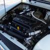
First things to look for when your SPI engine is not running quite right are air leaks. These leaks are usualy the ends of the little black, red and yellow capilary lines, they tend to split as shown below and play havoc with the vacuum reading of the ECU. They should be a very tight fit and nothing less than excellent condition.

Posted Image

The main one that seems to cause a problem is the one on the end of the short capilary identified with white, from the back of the inlet manifold to the fuel trap. Located on this port on the back of the inlet manifold, again identified with white.

Posted Image

The fuel trap looks like this, has one short black port and long green port.

Posted Image

While on the subject of capilary tubes and fuel traps, there is a known problem of fuel causing blockage in these tubes, mainly the one identified with green, attached to the long green port of the fuel trap and the ECU at the other end. The symptoms of this are, hesitation when accelerating usualy acompanied with a backfire in the inlet manifold and the car usualy bucks violently. The only fix for this is to remove the tubes along with the fuel trap and blow through, remove the ECU and insert some cotton wool into the MAP ( Manifold Absolute Pressure) sensor port and place the whole thing on a warm radiator over night. This is what is suggested in in a Rover service bulletin. Also ensure the capilary ends are in nothing less than excelent condition as above. The MAP sensor port as shown.

Posted Image

Other locations of air leaks are the breather system hoses and the evaperative emissions control system. Check all rubber hoses are in good condition, no cracks or splits. The main breather hoses to check are the ones supplying the purge valve and the charcoal canister. They usualy leak at the purge valve shown here.

Posted Image

Edited by Sprocket, 24 July 2011 - 04:47 PM.


#2 Sprocket

Sprocket

    Great on Injection faults

  • Members
  • PipPipPipPipPipPipPipPipPipPip
  • 7,266 posts
  • Location: Warrington
  • Local Club: Manchester Minis

Posted 04 February 2006 - 10:15 PM

If the engine turns over but fails to fire, first check the inertial switch. This switch some times has a tendency to trip when you have hit a sharp bump or pot hole. Its purpose is to stop the fuel pump spurting fuel all over the show in the event of an accident. Press the center of the top down to reset. This is not the only thing to stop the engine firing, but humour me and press it anyway.

Posted Image

If the engine fails to turn over then the imobiliser/ alarm may still be on. The alarm system sends a coded signal to the ECU telling it when the alarm is on or not and whether the engine is available to start or not. The alarm ECU is mounted on the bulkhead inside the car

[picture not avaiable]

The alarm diagnostic connector is green and protected with a black rubber cap as shown. The alarm need special equipment to test and Your local Rover Dealer will have this.

Posted Image

Edited by Sprocket, 24 July 2011 - 04:17 PM.


#3 Sprocket

Sprocket

    Great on Injection faults

  • Members
  • PipPipPipPipPipPipPipPipPipPip
  • 7,266 posts
  • Location: Warrington
  • Local Club: Manchester Minis

Posted 04 February 2006 - 11:08 PM

This subject has been amended with Rover service information and is in blue

The Oxygen (Lambda) sensor can be problematic causing either rich fueling or lean fueling. The only satisfactory way to check that this sensor is working correctly is by using a diagnostic tool such as the Crypton ACT. This tool wil show the voltage of the sensor swing from high volts (rich) to low volts (lean). This voltage swing happens in about a tenth of a second for a new sensor down to half a second for an old sensor needing replacement. To read more on Oxygen sensors follow this link http://www.picotech....bda_sensor.html
The Oxygen sensor and its location in the manifold seen from the offside of the car

Posted Image

Posted Image

And its connector

Posted Image

The diagnostic reaing the sensor volts and swings from high to low voltage

Posted Image

Posted Image

These sensors should be replaced roughly every 50,000 miles or five years checked for operation at 36000 or three years, and then every year after this. If there is any doubt as to its age or condition and you are having problems but unable to have a diagnostic check done, then it may be in your interest to replace the sensor and eliminate this as the fault, but first check everything else described in this topic. Drivebility symptoms of a faulty sensor include, hesitation, missfiring, elevated Hydrocarbon and CO readings not to mention poor idle. I have found that the relay for the heating element of the sensor can fail. This produces a Lean missfire at idle, yet all other driving conditions are fine. The reason for this is, at idle the sensor is not running hot enough and relys on the heater to keep it at operating temperature. The sensor reads constantly high voltage and the ECU thereby leans off the fueling. To test if this relay is faulty, the easiest thing to do is swap it with the electric fan relay next to it and see if the missfire dissapears.
The Oxygen sensor heater relay

Posted Image

The electric radiator fan relay

Posted Image

Direct replacement Bosch sensors are exactly the same as the OEM item and IMHO the only ones to use, Part Number 0258 003 193. Steer clear of the universal items, they cost little less and you have to cut and splice the connector from the old to the new. Don't buy this part from the likes of a Rover Dealer or any of the large Mini suppliers, buy it from a Bosch stockist and they can be located here http://www.boschauto...e...t&intType=1 and should only cost around £65 ( MiniSpares Center want just under £100)

Edited by Sprocket, 24 July 2011 - 04:26 PM.


#4 AlexM

AlexM

    One Carb Or Two?

  • Members
  • PipPipPipPipPipPipPip
  • 1,302 posts
  • Local Club: NMOC, ECMC

Posted 11 February 2006 - 10:38 PM

Truly excellent stuff here Sprocket!!

I'm understanding the injection system more and more!

#5 Bungle

Bungle

    Original Spamster

  • Members
  • PipPipPipPipPipPipPipPipPipPipPip
  • 28,971 posts
  • Location: Cornwall
  • Local Club: cornish mini club

Posted 11 February 2006 - 10:47 PM

this looks like a realy good guide

just glad i have a carb though

#6 Sprocket

Sprocket

    Great on Injection faults

  • Members
  • PipPipPipPipPipPipPipPipPipPip
  • 7,266 posts
  • Location: Warrington
  • Local Club: Manchester Minis

Posted 12 February 2006 - 01:05 AM

The air temperature sensor is the green plug and sensor mounted in the underside of either of the types of air filter, Standard or K&N. This sensor is used by the ECU to determine the density of the air entering the engine. The sensor does not have to totaly fail to cause issues with engine running. The sensor is a NTC (Negative Temperature Coefficient) thermistor, resistance rises as the temperature falls. The sensor element is constructed of two dissimilar metal wires fused together ( the bead ) at the tip of the senor, this generates a resistance that changes with temperature. The problem with this type of sensor is that it is prone to contamination with moisture which causes corrosion at this fused pint, generating a higher resistance. This happens over extended periods of time which causes them to read out. It will most likely read out low compared to the actual air entering the engine. The ECU thinks the air is denser (colder) than it is and adds more fuel to compensate, the engine does not need this extra fuel. This situation can only get worse as this excesive fuel now cloggs the pours of the oxygen sensor As the ECU struggles to control this sitution. A rich running condition is now present. I would only recomend replacing it with a new one. The sensor can only be acurately checked using a diagnostic tool and a calibrated thermometer. The Rover part number is NNK10001

Note: New information. Aparently this only contributes to 20% of the fueling equation with the main reasons for rich running being the Throttle position sensor and the Coolant temperature sensor.

When this sensor fails, causing rich running conditions, it usualy causes the Oxygen sensor to fail, if not corrected quickly. This usualy is not the case and hence why the Oxygen sensor fails as the carbon particles clog the pours of the sensor.

This is where those scam 'Power boost for your car' take advantage, or is that dissadvantage. The whole scam revolves round adding a specific value resistor in a parallel circuit to the air inlet sensor, thereby altering its resistance (high) and fooling the ECU into thinking the air is denser than it actualy is, and hence more fuel added by the ECU. Problem with this is, well the same as the symptoms below. Very little is gained, but more damage to the engine and its components results. Steer clear of these scams, some one is having a laugh and it'll be at you if you buy one. Just for comparison these resistors can be bought at the local Maplins for a few pence each.

Symptoms of rich running are black sooty spark plugs( make sure the correct plugs are used first NGK BPR6ES), rich missfire, eratic idle and elevated CO and Hydrocarbon emissions.

The sensor looks like this

Posted Image

Located here on the standard filter

Posted Image

And here on the K&N

Posted Image

Posted Image

To remove the standard air filter housing the three screws have to be removed first

Posted Image

And disconect the vacuum capilary, red in colour with a brown end, from here

Posted Image

This capilary supplys vacuum to the air cleaner inlet air temperature control system which operates a flap inside the housing, drawing air over the exhaust manifold, heating it, to aid smooth running in cold and freezing temperatures.

To remove the K&N filter this screw (similar to a jubilee clip) needs to be slackened

Posted Image

Word of warning when refitting this, make sure the filter surfaces and injection housing are free from oil, and only nip the screw enough to prevent the filter from moving. Excessivly tightening this screw will cause the filter to pop off over time. This IMHO is a design fault on the part of K&N. Some people have been known to use cable ties to keep the thing in place.

The K&N has no warm air system therefore the Red capilary is blocked off usualy with a screw suppied in the kit and is usualy tied back somewhere in the engine bay.

Posted Image

The sensor can be read when connected to the system with a diagnostic tool like the Crypton ACT

Posted Image

Edited by Sprocket, 24 July 2011 - 04:34 PM.


#7 the old git

the old git

    Stage One Kit Fitted

  • Noobies
  • PipPipPip
  • 51 posts
  • Local Club: P&SMOC

Posted 13 February 2006 - 08:23 PM

My son and I race in the Mighty Minis series, ours being a Super Mighty Mini. I am just the oily rag who looks after the car. On reliability, in 4years of racing the Super, we have never had a break down. Electrical/injection faults throughout the series, Supers and Standard Mighty Minis are rare bearing in mind the large number of cars racing. Those that do experience faults do so because of poor maintenance/laziness in preparation To overcome the problems associated with the MAP sensor to ECU pipe, we use the clear windscreen washer tube cut long enough to go round the pedal box to avoid it being melted/trapped. This has the advantage of being clear so you can see if oil vapour isgetting thro' to such an extent that the ECU becomes clogged. If retaining the original pipe and elbows, a common error is pushing the elbows on too far. This in effect, being a right angle, results in the pipe being sealed.

To overcome the fault with K&N air filters, which we use on the Super Mighty Minis, we stick a piece of sponge to the bonnet above it so that when it is closed it keeps it in place. It did not help the performance at over 100 mph when it used to pop off!!!!

#8 Sprocket

Sprocket

    Great on Injection faults

  • Members
  • PipPipPipPipPipPipPipPipPipPip
  • 7,266 posts
  • Location: Warrington
  • Local Club: Manchester Minis

Posted 19 February 2006 - 05:53 PM

The coolant temp sensor is the black sensor located in the inlet manifold. It can be found underneath at the right side of the manifold as you stand at the front of the car.

The coolant temperature sensor works on the same principle as the air temperature sensor, where by as the temperature falls the resistance rises or vica versa. Problems arise when this sensor reads out again for the same reasons as the air sensor. This has a more dramatic effect on the fueling of the engine. If its so far out the ECU may never leave the cold start and warm up programs wich are open loop control where the signal from the oxygen sensor is almost ignored. Again this sensor will usualy read out low. A permenantly rich condition will result. This sensor is connected directly to the ECU and then the ECU provides a signal to the Temp gauge on the dash. The gauge should read not quite mid way, just a little below the white line when the engine is warm. If it reads any different then there is a problem with the engine controlling the temperature. Or the sensor is faulty. On that note it is worth while checking the plug connectors as these can suffer contact corossion. This sensor can only be acurately checked with the diagnostic and a calibrated thermometer. If there is any doubt and you are unable to have a diagnostic done then I would advise replacement but thats only if you are suffering a rich condition and the temp gauge reads below and never anywhere near the mid white line, not above as this would probibly be a cooling system fault.

Again if this sensor is faulty and causes an over rich mixture for long periods, the Oxygen sensor will usualy fail too, as discused above in the air sensor section.

It also may be worth noting that if the thermostatic control is not working correctly on the cooling system that both a hot and cold condition can result so it is in your best interest to fault find this first. For instance if the cooling system fault causes cooler engine temperatures then the ECU will see this as if the engine is still warming up and stay in cold start.

Here is the sensor removed from the manifold, it differes some what from the ones used on the carb engines.

Posted Image

And here is its location on the underside of the manifold in line with the water heating pipes( this picture is taken with the manifold removed and upside down)

Posted Image

Edited by Sprocket, 24 July 2011 - 04:37 PM.


#9 Sprocket

Sprocket

    Great on Injection faults

  • Members
  • PipPipPipPipPipPipPipPipPipPip
  • 7,266 posts
  • Location: Warrington
  • Local Club: Manchester Minis

Posted 19 February 2006 - 07:55 PM

Adjusting the throttle cable is not as simple as it is for the carb engines, and certain procedures must be followed for it to be correct. This some times known as Indexing the Throttle.

To check if the throttle cable is adjusted correctly the IAC (Idle Air Control) stepper motor needs to be 'set'. This is achieved by turning the ignition to on but do not start the engine, then operate the throttle linkage to full open throttle. Do not use the throttle pedal as this will not work.

Operate this linkage and not the pedal

Posted Image

This sets the stepper motor to the correct position to allow you to adjust the cable.

Adjust the cable here using two 13mm spanners
Posted Image

To achieve equal spacing on what is called the lost motion link( middle prong centralised between the other two prongs)

Posted Image

Do not under any circumstance adjust this screw unles you have access to a diagnostic unit that is capeble of tuning the idle speed. Idle speed cannot be set without this diagnostic. The stepper motor plunger can be seen to the left, it acts on this screw adjusting the idle speed

Posted Image

Once the cable has been adjusted the ignition can now be turned off.

Here is the connector for the IAC stepper motor

Posted Image

Idle speed can only be set using a diagnostic like the Crypton ACT. it will tune the stepper and tell you to adjust the idle speed screw so that the stepper motor is in the correct place at idle speed. The ECU then modulates the stepper motor to achieve 850rpm.

Posted Image

Problems arise when this idle speed screw has been adjusted without the diagnostic causing in worst cases the stepper to be eaither at zero steps and unable to lower idle speed or full steps and unable to increase idle speed.

Posted Image

A diagnostic check is the only way to check the tune of the IAC stepper motor and idle speed. Stepper motors do fail. There are four coils in the stepper motor and five pins on the connector. If one of these coils fail then the ECU will not be able to control the idle speed correctly. These as far as I am aware are available as a seperate part from Rover dealers, but then there are not many of these left.

A note on stiff throttle cables, these can obviously cause the idle speed to vary and not at any regular pattern either, if the idle rests at above 1750 rpm then there is a problem with the cable, it may have excessively sharp bend, kinks, or itself be stiff. If this is the case, when you lift off the throttle and the idle stays high, try lifting the pedal with your toe. If the idle drops back to normal then the throttle cable is stiff. I would only recomend replacing this. Trying to lubricate the inner cable will work for a short period but sooner or later you will be back to where you started. WD40 is useles for this purpose. Throttle cables are normaly dry running, using a nylon or tefflon lining. The linkages can become stiff on perticularly old systems and could benifit with a light oiling. Throttle cable part number is SBB10187 and should cost roughly £10 though you'll use more than that in time and effort fitting it.

Edited by Sprocket, 24 July 2011 - 04:45 PM.


#10 vitruvian

vitruvian

    Learner Driver

  • Noobies
  • PipPip
  • 16 posts

Posted 23 February 2006 - 03:33 PM

I got K&N open type air filter and I would like to return to original setting (with original air filter housing). Problem is I couldn't locate the red capilary, is it really need it???

#11 Sprocket

Sprocket

    Great on Injection faults

  • Members
  • PipPipPipPipPipPipPipPipPipPip
  • 7,266 posts
  • Location: Warrington
  • Local Club: Manchester Minis

Posted 23 February 2006 - 07:54 PM

Yes, otherwise the air would be drawn over the exhaust manifold all the time and would do nothing for fuel consumption or power.

Edited by Mini Sprocket, 24 November 2006 - 12:14 AM.


#12 vitruvian

vitruvian

    Learner Driver

  • Noobies
  • PipPip
  • 16 posts

Posted 24 February 2006 - 12:19 AM

Thank you for the info, I guess I have to stick with Open type filter.

#13 AlexM

AlexM

    One Carb Or Two?

  • Members
  • PipPipPipPipPipPipPip
  • 1,302 posts
  • Local Club: NMOC, ECMC

Posted 24 February 2006 - 09:13 PM

Success Story

Injection problems

#14 m3ntalist

m3ntalist

    Ring Runner 2005

  • Members
  • PipPipPipPipPipPipPip
  • 924 posts

Posted 25 February 2006 - 10:46 PM

I think I need to read through this a few times, or print out the whole thing.

If the engine has been taken out and replaced do you need the diagnostic tool to set it up again?

The idle is going nuts at the moment, as it gets warmer it seems to get worse...

#15 BRM

BRM

    Starting My Mini Up

  • Noobies
  • Pip
  • 1 posts

Posted 27 February 2006 - 08:34 AM

I think I need to read through this a few times, or print out the whole thing.

If the engine has been taken out and replaced do you need the diagnostic tool to set it up again?

The idle is going nuts at the moment, as it gets warmer it seems to get worse...


It sounds like one of the small pipe connectors is not attached or has been blocked. There are two attache below the inlet manifold. Check atta re tther and pipes are clear. Sometimes if they are pushed on too bar the tube gets blocked.

One runs from the ECU via the vapour trap to the manifold. The other goes to the air filter housing.


0 user(s) are reading this topic

0 members, 0 guests, 0 anonymous users