Step 13.Now re-fit the shock absorber back into its location and bolt it up. Also re-fit the fuel tank back into its location, making sure the tank strap is sat properly and is tight. Re-fit the wheel and lower back onto the ground.

The same steps apply to both sides at the rear, the only difference being on one side (unless you have twin tanks) you can get at the shock absorber without having to move the tank.
Please be aware though that it will take a few days of trial and error before you get the ride height how you want it and level all the way round. Setting each Hi-Lo by how many threads you can see doesn’t work, and neither does using a tape measure straight after you fit them. You need to let them bed in for a few miles, then adjust each one a little at a time until it is how you want it.
FrontTo do this you will need a cone compression tool.
Step 1.Loosen the wheel nuts on the side you’re going to be working on.
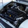
Step 2.From under the bonnet, undo and remove the subframe tower bolt from the bulkhead cross member (34mm socket)
 Step 3.
For those who haven’t seen or know what a cone compression tool is, here you go…

As you can see, there are 5 parts to it. There are two bars that look the same with threads at each end and a nut on one end. There is a different thread on these on the oppostite end to the nut, on one it is coarse and the other is fine (can’t remember the thread size). The coarse threaded one is for the earlier canes and the fine threaded one is for the later cones (post 84?).
Screw the bar with thread all the way down to the other bar that fits your cone thread and insert it through the subframe tower bolt hole and screw it into the cone as far as it will go.


Next take the ‘T’ shaped part and slide it over the top of the threaded bar and make sure the base is sat flush on the cross member.

Then screw the handle part onto the threaded bar. Tighten this down by h and as tight as possible, then I use a short bar around 8” long to tighten it a couple more turns. If you do this while the car is still sat on the ground, it uses the weight of the car to compress the cone so you don’t have to strain trying to compress it so far yourself.
 Step 4.
Now that the cone is compressed, jack and support the car in a safe way on level ground, using axle stands where needed.
Step 5.Remove the wheel and you’ll see a shorter version of the cone that you removed from the rear suspension tucked away in the subframe.


 This topic is locked