nice looking pannel by the way ru55boy how did you put the lettering on to it?
Cheers mate, I just took it into a key cutters / shoe repair shop in the high street.


Speeding Along Now

Posted 12 February 2009 - 06:19 PM
nice looking pannel by the way ru55boy how did you put the lettering on to it?
On Sabbatical

Posted 19 February 2009 - 06:08 PM
Speeding Along Now
Posted 19 February 2009 - 08:12 PM
Hi Ru55boy,
Sorry I forgot all abut this.
Tell me what sort of switch it is you are using and I'll come up with a circuit for you. From what you've said it sounds like a conventional SPST switch with illumination. Do you want the lamp in the switch to flash in time with the seperate warning lamp? Do you want anything lit as a locator?
On Sabbatical
Posted 19 February 2009 - 09:55 PM
Edited by Dan, 20 February 2009 - 12:06 PM.
Speeding Along Now
Posted 20 February 2009 - 07:12 PM
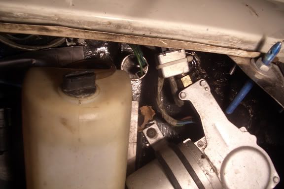
Does your car use two flasher units or the later single flasher system? Also is the third terminal on the switch for LED power or for LED earth? Does the LED have a built in limiting resistor?
On Sabbatical
Posted 20 February 2009 - 08:56 PM
Speeding Along Now
Posted 20 February 2009 - 11:36 PM
You should have 2 flashers on a '79 car. One round one behind the clocks for the indicators and a square one in the engine bay for the hazards. If that's not the case I'll have to start again.
Does the switch LED only light when the switch is closed? I'm just a little concerned that since it's a permanantly powered circuit the LED will be running constantly and be a battery drain, albeit a small one.
Last questions, promise. It's just tricky to come up with a circuit when I don't know exaclty how one of the components behaves! I've done a drawing though and it's a really simple circuit, no trouble to put together. You'll have to buy specific relays. Answer this last question and if it all seems to work I'll sitck up the drawing.
On Sabbatical
Posted 21 February 2009 - 12:47 AM
Speeding Along Now
Posted 21 February 2009 - 08:55 AM
What colour wires does the original switch have?
On Sabbatical
Posted 21 February 2009 - 12:35 PM
 scan0002.jpg 1.2MB
59 downloads
scan0002.jpg 1.2MB
59 downloads
Speeding Along Now
Posted 21 February 2009 - 05:20 PM
One Carb Or Two?
Posted 22 March 2009 - 09:20 AM
hazard_withour_LED.jpg 1.15MB
18 downloadsOne Carb Or Two?

Posted 20 April 2011 - 03:09 PM


0 members, 0 guests, 0 anonymous users


