Engine's back in, all the plumbing hoses have been flushed as well and will be buttoned up tomorrow. Just a couple of small things to do on the water plumbing and the engine will be ready to start in the chassis for the first time! Here's to hoping the kids going back to school in a week or two doesn't curtail the time I'll need to get her up and running soon.

Z-cars Monte Carlo, Intercooled Hayabusa Turbo, Usa Edition
Started by
Monte Busa
, Oct 14 2005 01:36 AM
380 replies to this topic
#361

Monte Busa
-
- Noobies
-

- 681 posts
Super Mini Mad
- Location: Michigan, USA
Posted 20 August 2012 - 04:14 AM
#362
Birdman
-

- Members
-
- 400 posts
Speeding Along Now
- Location: Central Oregon
Posted 20 August 2012 - 09:54 AM
Good to hear it's getting close.
#363
Monte Busa
-
- Noobies
-
- 681 posts
Super Mini Mad
- Location: Michigan, USA
Posted 26 August 2012 - 11:05 PM
Ok, thought I'd show some pictures of my latest progress. I've been spending time pushing ahead on the turbo installation, water plubing, various aluminum fabrication.
Turbo installation,. showing the Swaintech ceramic coated heat management treatment
 IMG00036-20120826-1744.jpg 95.39K
246 downloads
IMG00036-20120826-1744.jpg 95.39K
246 downloads
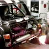
The finalized rear plumbing for the dry sump, fuel swirl pot/anti-surge tank, and engine/dry-sump breather
IMG00037-20120826-1745.jpg 113.62K
162 downloads
"There is an engine somewhere in there, I promise". Overflow tank for cooling system
IMG00038-20120826-1745.jpg 114.92K
113 downloads
Party completed fabrication of a combination fuel tank top support and radiator support. it will tie back to the front firewall, and clamps the fuel tank in the middle, then folds down into legs that will jut out to the radiator top mounts...intricate piece.
IMG00039-20120826-1746.jpg 102.61K
106 downloads
Simple but effective brake cooling ducts. 2" aluminum - will tie into brake duct hose and to scoops in the Ultimini valance
IMG00040-20120826-1746.jpg 79.58K
127 downloads
IMG00041-20120826-1747.jpg 79.32K
41 downloads
Box sections added in lower rear firewall to clear the intake and exhaust pipes
Turbo installation,. showing the Swaintech ceramic coated heat management treatment
IMG00036-20120826-1744.jpg 95.39K
246 downloadsThe finalized rear plumbing for the dry sump, fuel swirl pot/anti-surge tank, and engine/dry-sump breather
IMG00037-20120826-1745.jpg 113.62K
162 downloads"There is an engine somewhere in there, I promise". Overflow tank for cooling system
IMG00038-20120826-1745.jpg 114.92K
113 downloadsParty completed fabrication of a combination fuel tank top support and radiator support. it will tie back to the front firewall, and clamps the fuel tank in the middle, then folds down into legs that will jut out to the radiator top mounts...intricate piece.
IMG00039-20120826-1746.jpg 102.61K
106 downloadsSimple but effective brake cooling ducts. 2" aluminum - will tie into brake duct hose and to scoops in the Ultimini valance
IMG00040-20120826-1746.jpg 79.58K
127 downloads
IMG00041-20120826-1747.jpg 79.32K
41 downloadsBox sections added in lower rear firewall to clear the intake and exhaust pipes
Edited by Monte Busa, 28 August 2012 - 01:15 AM.
#364
Rogue Se7ens
-

- Noobies
-
- 125 posts
Mini Mad
Posted 30 August 2012 - 06:05 AM
WOW! Great looking stuff, I enjoy following the progress.
#365
Jeffreypang911
-

- Members
-
- 237 posts
Mini Mad
Posted 31 August 2012 - 01:05 AM
Pretty, love those AN fittings, knowing how expensive they are.
What size tank? 10GAL?
What size tank? 10GAL?
#366
Monte Busa
-
- Noobies
-
- 681 posts
Super Mini Mad
- Location: Michigan, USA
Posted 01 September 2012 - 07:07 PM
It's about 8 gallon, but just over 7 net with the FIA FT3 bladder in it.
What size tank? 10GAL?
#367
Monte Busa
-
- Noobies
-
- 681 posts
Super Mini Mad
- Location: Michigan, USA
Posted 12 September 2012 - 03:13 AM
Hi Guys. Fortunately or unfortunately, my wife convinced me to buy a vacation home, so cash for toys will be tight for a bit, so updates may slow a little. Don't worry though progress continues! I'll be getting my new wing section carbon front splitter and a few other tasty bits in a week or two. I'll post pictures when I do!
#368
Birdman
-
- Members
-
- 400 posts
Speeding Along Now
- Location: Central Oregon
Posted 12 September 2012 - 12:48 PM
Is the car running? Have you had it out for a spin yet?
#369
Monte Busa
-
- Noobies
-
- 681 posts
Super Mini Mad
- Location: Michigan, USA
Posted 12 September 2012 - 08:54 PM
Nope, not quite running yet...
Is the car running? Have you had it out for a spin yet?
#370
Monte Busa
-
- Noobies
-
- 681 posts
Super Mini Mad
- Location: Michigan, USA
Posted 04 December 2012 - 01:53 AM
Things are still moving along, albeit slowly. I just got my wing section splitter (flat top Selig 1223) from Mike Devins and fit it up yesterday. 1.5" ground clearance! End plates for the splitter will be designed next.
Attached Files
-
selig splitter.jpg 64.39K
80 downloads
Edited by Monte Busa, 04 December 2012 - 01:54 AM.
#371
Birdman
-
- Members
-
- 400 posts
Speeding Along Now
- Location: Central Oregon
Posted 04 December 2012 - 10:26 AM
Good to see you still making progress Aric.
#372
cptkirk
-
- Members
-
- 1,799 posts
Camshaft & Stage Two Head
- Location: West Sussex
- Local Club: B.M.C. + Chiminiclub
Posted 04 December 2012 - 12:43 PM
Things are still moving along, albeit slowly. I just got my wing section splitter (flat top Selig 1223) from Mike Devins and fit it up yesterday. 1.5" ground clearance! End plates for the splitter will be designed next.
Holy Crap Aric, you are going full on with the aero.
Can I ask what was the driving force behind using a wing section for a splitter? I ask because after researching aero for my diffuser I was under the impression that to create good ground effects you need a flat throat to flat bottom of no more than 3deg's or a gentle curve to flat bottom from the front splitter. The air then travels fast under the flat floor at low pressure and then as the air slows down as it expands it becomes almost vacuumous as it exits via the diffuser which in turn sucks the car to the ground. The air dam that is created above the a front splitter creates high pressure and by way of Bernoullis effect the the high pressure is drawn to the low pressure (the low pressure being the fast moving air under the splitter) therefore giving downforce at the front of the car.
It is my belief that if you have a wing section at the front under a saloon type car (with a flat bottom) you will create air that goes from fast to slow to fast to slow, rather than just fast to slow. Conversely with a wing on the front of a single seater the slowing air after the wing can be released to atmosphere and will join, once again, with the low pressure air that flowed over the top of the wing section creating downforce (just fast to slow).
As you might know from anything I have previously posted I am not trying to start arguments or poke holes, I am genuinely interested in your thought process behind using a flat topped wing section on the front of the car. Also from your picture I cant tell the whole story about what you are doing with the flat floor in relation to the front wing, so you might have the floor mating with the wing section so that it doesnt allow the air to slow up once past the lowest part of the section. I look forward to being enlightened.
All that said and done, the car is looking bad ass.........
#373
Monte Busa
-
- Noobies
-
- 681 posts
Super Mini Mad
- Location: Michigan, USA
Posted 04 December 2012 - 05:02 PM
Thanks for the compliments.
The philosophy behind the wing section splitter is manifold. The most important aspect is that the wing section will be much less sensitive to pitch changes and ride height than a flat plate, making the actual downforce generated AT the splitter (front of the car) more effective. You can actually funnel more air under a wing section than a flat plate splitter at the same ride height as well and get a real venturi effect vs. just creating a stagnation zone pressure differential that a flat plate allows. Flat plate splitters can also easily get "choked" or pinched off if the ride height gets too low, destroying any intended longitudinal feed of the rear difusser. WIng section splitters can be run lower to the ground without pinching off, and as the ride height reduces, the aero effect is maganified greatly. Flat plate splitters will also likely have completely detached airflow right after the front edge, which makes management of the downforce outside of center of the splitter (within the wheels wells) very difficult (see next paragraph on why this important).
My research suggests that a very large proportion of the total front downforce is generated by what happens in the wheels wells, via either brute force extraction of high pressure from the wheel well areas, or ideally, managing to develop a diffuser action in addition to air extraction. Sports racers have started to use integrated wheel well diffusers to very good effect, as LeMans racers have been doing for some time. Given the very short front overhang of the Mini, using a wing section to do this makes sense as the diffuser cannot extend back any farther than the front of the tires, otherwise it will foul the suspension. My strategy is to use the front wheel well vents (rear facing) and front fender top louvered vents to hopefully develop positive suction within the wheel wells, helping the wing section within the wheel wells attached and to function as a diffuser should.
Lastly, Pilbeam has used wing section front splitters for a number of years as well to good effect in both their full zoot LMPs as well as club racers, so I'm flattering them by my imitation :)
On the topic of feeding the rear diffuser, there is two things to consider. The first is what you stated, namely that sufficient high velocity air volume has to be present at the transition point of the diffuser to make it effective (which, as long as the splitter doesn't pinch off can be done effectively). The second thing to consider is that leakage from the side of the car needs to be minimized to make the diffuser effective. Side splitters work well for this, but I'm also planning on adding fences both longitudinally under the car to keep the centerline flow volume where it needs to be to feed the diffuser transition point and possibly along my side splitter countour and the rear wells to accomlish this.
Much fun and experimentation to come!
Edited by Monte Busa, 05 December 2012 - 03:55 PM.
#374
cptkirk
-
- Members
-
- 1,799 posts
Camshaft & Stage Two Head
- Location: West Sussex
- Local Club: B.M.C. + Chiminiclub
Posted 04 December 2012 - 05:40 PM
All great info, thanks for sharing and gives me something to look into. Cant wait to see it finished....
#375
cptkirk
-
- Members
-
- 1,799 posts
Camshaft & Stage Two Head
- Location: West Sussex
- Local Club: B.M.C. + Chiminiclub
Posted 28 June 2013 - 05:37 AM
Hi Aric - any news on the build?


0 user(s) are reading this topic
0 members, 0 guests, 0 anonymous users


