Jump to content


Photo
- - - - -

Electronic Ignition Problems


  • Please log in to reply
21 replies to this topic

#1 jam2005

jam2005

    One Carb Or Two?

  • Members
  • PipPipPipPipPipPipPip
  • 1,297 posts
  • Local Club: None

Posted 19 February 2006 - 07:35 PM

I purchased a Lumenition Magnetronic ignition system for my dizzy from a forum member. They assured me that the system was working and I trust then on that.

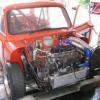
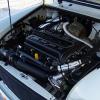
I've fitted it all up and wired in in but just refuses to work. If used a combination of different earth (-) and positives (+) but none seem to work. If checked the distance from the unit and the disc and all seems fine. The only things I can think of at the moment is that the unit does not work or I am missing out something very obvious, probably the latter.

The only difference to the instructions to the wiring I have done is that I have connected my positive (+) to fuse 1 on the fuse box (ignition stage II) as my coil does not provide a 12v output (it's a 1987). Also the earth is not connected to the negative (-) of the coil, it is connected to the bodywork. I have ensured that this is bare, clean metal and also tried using the main engine earth strap.

Would be grateful if someone could help asap as the mini is dead. Everything worked fine before these were changed.

Cheers, Jam2005 ;D

#2 Wil_h

Wil_h

    Up Into Fourth

  • Members
  • PipPipPipPipPipPipPipPipPip
  • 3,244 posts

Posted 19 February 2006 - 08:49 PM

If I've read that right then you've connected the black wire to the chassis rather than the -ve of the coil?

It NEEDS to go to the -ve of the coil, otherwise how does it turn the coil on and off?

Wil

#3 Sprocket

Sprocket

    Great on Injection faults

  • Members
  • PipPipPipPipPipPipPipPipPipPip
  • 7,266 posts
  • Location: Warrington
  • Local Club: Manchester Minis

Posted 19 February 2006 - 10:22 PM

The live should come from the first fuse which is powered with position II on the ignition switch, white wire one side and green wire the other side of the fuse

Edited by Mini Sprocket

#4 jam2005

jam2005

    One Carb Or Two?

  • Members
  • PipPipPipPipPipPipPip
  • 1,297 posts
  • Local Club: None

Posted 19 February 2006 - 10:33 PM

Nar it's fuse 2 (see pikky).

I also want to uprate the coil to a sports one. Do I have a ballast or not ballast coil? It's a 1987 and has black and white wires going to the (-) terminal. Don't think it has a resistor though... unless the suppressor on the (+) terminal is a resistor?

I was thinking one of these... Clicky

Cheers, Jam2005 ;D

Attached Files


#5 Sprocket

Sprocket

    Great on Injection faults

  • Members
  • PipPipPipPipPipPipPipPipPipPip
  • 7,266 posts
  • Location: Warrington
  • Local Club: Manchester Minis

Posted 19 February 2006 - 10:41 PM

Yup yup, it is fuse one, you are correct. i shall edit the above

#6 rob3

rob3

    Stage One Kit Fitted

  • Noobies
  • PipPipPip
  • 99 posts

Posted 19 February 2006 - 10:45 PM

As above it NEEDS to be connected to the -VE of the coil or it WILL NOT!! work

#7 jam2005

jam2005

    One Carb Or Two?

  • Members
  • PipPipPipPipPipPipPip
  • 1,297 posts
  • Local Club: None

Posted 19 February 2006 - 11:25 PM

Ok cheers ;D

So with my ar being a 1987 will the system be ballast or non balast? Im sure that it is balast but I can't see a resistor anywhere, only a suppressor.

#8 Wil_h

Wil_h

    Up Into Fourth

  • Members
  • PipPipPipPipPipPipPipPipPip
  • 3,244 posts

Posted 20 February 2006 - 07:43 AM

It is a ballast resistor system. There is no 'resistor' as such just a high resistance wire.

If you pull the +ve wire out of the loom it should be pink/white with resistor written on it.

#9 jam2005

jam2005

    One Carb Or Two?

  • Members
  • PipPipPipPipPipPipPip
  • 1,297 posts
  • Local Club: None

Posted 20 February 2006 - 09:39 AM

So how do I wire in one of these? Clicky

Where do I put the white piece? ;D

#10 dklawson

dklawson

    Moved Into The Garage

  • TMF+ Member
  • PipPipPipPipPipPipPipPipPipPipPip
  • 10,923 posts
  • Name: Doug
  • Location: Durham, NC - USA
  • Local Club: none

Posted 20 February 2006 - 01:14 PM

As stated above, the Lumenition (+) connection needs full +12V and the (-) connection MUST go to the coil (-) terminal.

As for "how do I wire in one of these"? Do you mean the coil or the ballast resistor? Presumably you mean both. To wire in a Ballast coil AND it's external Ballast Resistor you have several steps to perform. Start by getting your existing Lumenition system working. NEVER change several things at once.

Once you've got the Lumenition working, if you still want a new coil, start by recording/photographing your existing coil and its connections. IF your car does have the pink wire coming from the ignition switch you should replace it (all of it) with a "standard" non-resistance wire of similar size. One end of that new wire goes to one side of the ballast resistor (either one... it doesn't care), the other wire end goes to the ignition switch. The other side of the ballast resistor needs a wire from it to the (+) terminal on your new ignition coil. The coil (-) terminal will hook up to your Lumenition system as before. You're not done yet. There should already be another wire on your existing coil's (+) terminal. You should be able to trace this wire over to the starter solenoid. This wire needs to connect to your new coil's (+) terminal.

I don't think I missed anything. Others can correct this as necessary.

#11 jam2005

jam2005

    One Carb Or Two?

  • Members
  • PipPipPipPipPipPipPip
  • 1,297 posts
  • Local Club: None

Posted 20 February 2006 - 07:39 PM

Cheers for that DK ;D

I got the igntion running a few hours ago by connecting the (-) on the igntion module to the (-) of the coil. All was running ok and there the engine cut out after about 20 seconds. Checked all the connections and a (-) feed was slightly lose so I reconnected it correctly. If checked and there now is a feed on both the (+) and (-) of the ignition module. Cant seem to get it to work agan though :o

Need some serious help now. Could the coil have blown? Im think of fitting my old points and condenser to check the system and then starting from scratch at fitting the electronic ignition module again. Im thinking that either the coil or the electronic module is fried?!

Cheers for the help so far, Jam2005 :o

#12 dklawson

dklawson

    Moved Into The Garage

  • TMF+ Member
  • PipPipPipPipPipPipPipPipPipPipPip
  • 10,923 posts
  • Name: Doug
  • Location: Durham, NC - USA
  • Local Club: none

Posted 20 February 2006 - 09:31 PM

Sorry about the short life of your ignition.

Don't take this wrong but since I find myself explaining points ignitions a lot I put together a PDF about them. Please copy and read over:
http://home.mindspri...tsIgnitions.pdf
There is some troubleshooting information in the document that may help.

I agree that at this time you should put the points back in and make sure the rest of the ignition system is working as you expect. Then worry about the Lumenition or other ignition changes.

In answer to your direct question, I don't think that you've done any damage to the coil.

#13 Dan

Dan

    On Sabbatical

  • TMF+ Member
  • PipPipPipPipPipPipPipPipPipPipPip
  • 21,354 posts

Posted 20 February 2006 - 10:34 PM

I think it's quite likely that it's the highly sensitive electronic device that you've blown up by wiring it up wrong rather than the basic electrical transformer.

Don't fit a sports coil with the Magnetronic, the only uprated coil you can fit is the Luminition one you have found at Minispares but it's really not worth it.

If you do insist on using it then wire it as DK says. The wire you have already connected to the red wire of the Magnetronic will be your supply to both the new ballast resistor and the Magnetronic. The existing pink/white wire to the coil is the current ballast and you need to tape over the end of it so it's insulated, and tape it back to the loom out of the way. The white/yellow wire needs to be connected directly to the coil positive terminal, so that it bypasses the ballast resistor and the positive terminal also needs connecting to the output of the ballast resistor.
The Magnetronic will need to be connected to the input of the ballast so that it is connected directly to the feed you have added. The negative side of the coil is then connected to the white/black wires on the existing coil. One of these is the current connection to the points/condensor but it'll be hard to track down which is which without slicing open the loom so connect the switching terminal of the Magnetronic to the original white/black at the distributor connection where you disconnected the points. The other white/black is the tachometer feed. The Magnetronic unit is earthed through the distributor body so you don't need to worry about finding an earth for it, the black wire to it is the switching output that controls the coil. If you get any of this wrong then the coil and ignition won't survive very long as you have found out.

#14 jam2005

jam2005

    One Carb Or Two?

  • Members
  • PipPipPipPipPipPipPip
  • 1,297 posts
  • Local Club: None

Posted 20 February 2006 - 10:45 PM

So your suggesting that the electronic ignition has probs blown and not the coil? How can I test the coil?

#15 Dan

Dan

    On Sabbatical

  • TMF+ Member
  • PipPipPipPipPipPipPipPipPipPipPip
  • 21,354 posts

Posted 20 February 2006 - 10:50 PM

I reckon so. If the coil works with your points and condensor as it did before then it's definitely the Magnetronic. I can't think that you've damaged the coil as you basically had it completely disconnected by earthing out the switching output of the unit. It depends on how you connected up the live, if the coil has been accidentally connected to 12v then it could well be that that's melted down.


1 user(s) are reading this topic

0 members, 1 guests, 0 anonymous users