Jump to content


Photo
- - - - -

Radius Arm & Camber Bracket - Is This Gap Normal?


  • Please log in to reply
18 replies to this topic

#1 colinu

colinu

    Super Mini Mad

  • TMF+ Member
  • PipPipPipPipPipPip
  • 517 posts
  • Location: Santa Rosa, California USA
  • Local Club: MOASF

Posted 16 August 2012 - 06:59 AM

Folks,

Refurbishing and rebuilding my rear subframe and started to put the radius arms back on this evening. I'm using new camber brackets. I'm doing a "loose" fit to make sure everything goes together OK - i.e. not tightening any of the bolts in the brackets yet so the bracket can float a little.
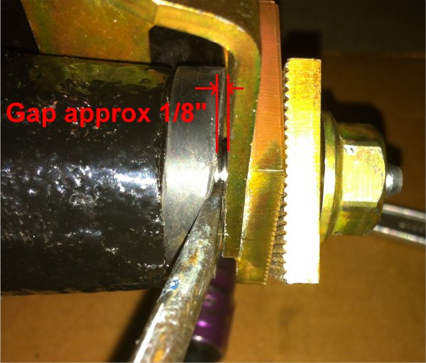
However, what I see is an approx 1/8 inch gap between the thrust washer on the end of the arm and the camber bracket... even if the bracket is push inwards as far as it will go (see picture below). Is that normal, or should I put an 1/8 inch additional washer in the gap (one with a diameter larger than the rubber seal ring)??? The gap does close when everything is torqued up... but only because the bracket is bending slightly.

Please put my mind at ease :wacko:

Note: I've tried three sets of brackets from different suppliers (the original but knackered/unusable fixed brackets, camber adjustable, and toe/camber adjustable) and all show the same issue.

Also... yes I know many will say "don't use adjustable brackets - modify a fixed set to your geometry requirements"... yes I could do that, but I don't have a good set of fixed brackets to hand. I'm going to use the Minisport toe/camber ones in the picture, then when I'm happy with the geometry I'll weld the slotted adjustment plate in place.

Cheers,
Colin.

Posted Image

#2 colinu

colinu

    Super Mini Mad

  • TMF+ Member
  • PipPipPipPipPipPip
  • 517 posts
  • Location: Santa Rosa, California USA
  • Local Club: MOASF

Posted 16 August 2012 - 08:33 PM

Anyone?

#3 bmcecosse

bmcecosse

    Crazy About Mini's

  • Members
  • PipPipPipPipPipPipPipPipPipPip
  • 9,699 posts
  • Local Club: http://www.srps.org.uk/

Posted 16 August 2012 - 08:36 PM

As you suspected - the answer is to USE THE PROPER BRACKETS - and adjust the hole position to give you the toe and camber you need. I wouldn't trust these brackets to drive down to the newsagents..........

#4 J960mayfair

J960mayfair

    Mini Mad

  • Members
  • PipPipPipPip
  • 267 posts
  • Local Club: Medway Mini Club

Posted 16 August 2012 - 08:41 PM

quick hijack im sorry! i have just fitted standard arms onto mine with standard brackets will all tracking be out?

thanks

#5 tiger99

tiger99

    Crazy About Mini's

  • Members
  • PipPipPipPipPipPipPipPipPipPip
  • 8,584 posts
  • Location: Hemel Hempstead

Posted 16 August 2012 - 09:01 PM

Standard arms, standard brackets, will put it somewhere near correct if the subframe is of good quality and neither it nor the radius arms have ever been bent. I would still be inclined to have it checked, and the appropriate adjustments made if necessary. In particular, you really do not want the slightest trace of toe out on the rear wheels, which is extremely bad for stability. It is remarkable how much difference going from about 3 mm toe in (correct) to 3 mm toe out makes, it becomes rather dangerous. You don't really want positive camber on the rear wheels either, parallel or a trace of negative, say half a degree, works best. But the effect of changing camber is rather mild compared to toe out.

#6 colinu

colinu

    Super Mini Mad

  • TMF+ Member
  • PipPipPipPipPipPip
  • 517 posts
  • Location: Santa Rosa, California USA
  • Local Club: MOASF

Posted 16 August 2012 - 09:37 PM

I appreciate the opinions on not using adjustable brackets (and respect/understand the reasons), but still no answer to my gap question.
So... Is that 1/8" gap normal??? and/or is it OK to close it by torquing everything up, should I fit a packing washer, or do I look for what's causing that gap?
Remember I'm even seeing that gap when I try using the original/standard set of brackets.

#7 tiger99

tiger99

    Crazy About Mini's

  • Members
  • PipPipPipPipPipPipPipPipPipPip
  • 8,584 posts
  • Location: Hemel Hempstead

Posted 17 August 2012 - 02:51 PM

No, that gap is not normal.

I can't say much about the adjustable camber bracket, except that they are notorious for failing, but a standard bracket should fit correctly without a gap, as you will expect. I can also see why they have a bad reputation for failing, they appear to have been plated, and as well as being badly designed, there is the risk of hydrogen embrittlement. I would not risk one of these, even welded up, but use a solid bracket, adjusted as necessary.

Now, what could be wrong? The radius arm assembly sits between the web of the subframe side member and the camber bracket, length determined by radius arm (which must closely match the pivot pin) plus two thrust washers. I doubt that you have a non-standard radius arm or pivot pin, so it is down to either the thrust washers being too thin or the subframe dimensions being incorrect. The washers are easy to check, they should both be the same thickness, and in any case are special, with an eccentric lubrication groove, so they are unlikely to be confused with anything else. However, I can't see the washer clearly in your picture. They ought to be about 3 to 4 mm thick, from memory.

It is quite possible that the subframe side members have been welded to the crossmember in the wrong position, too far inboard, and it would not take much to give you that gap.

I suggest that you fit a large washer, larger than the diameter of the sealing ring, between the inner thrust washer and the side member web, to take up the gap at that end, as it is a less stressed area and the washer will not get in the way of any attempts at tracking and camber adjustment. But first check that the web has not been pushed inwards and bent somehow, as that could also explain it.

#8 colinu

colinu

    Super Mini Mad

  • TMF+ Member
  • PipPipPipPipPipPip
  • 517 posts
  • Location: Santa Rosa, California USA
  • Local Club: MOASF

Posted 17 August 2012 - 04:38 PM

Tiger,

Many thanks for the reply. I ended up thinking along the same lines as your suggestion... last night I "solved" the problem by fitting a washer between the inner thrust and the subframe webbing, and elongating the bracket mounting holes a little. Brought the gap to less than 1/16".
As this gap was the same on both arms/brackets I'm putting it down to bad "manufacturing tolerences" of the subframe. The subframe webbing doesn't seem to be dented, and the shafts and thrust washers are to spec (I checked against another new one I have lying around).
Regarding the adjustable brackets and their bad reputation for failing... although I've use the same adjustable brackets on my other Mini with no problems (fitted 12 years ago - and seen a LOT of abuse) I do take your points and will most likey modify a set of standard brackets. However or the time being I'll fit the adjustables as I need to get the Mini back on four wheels so I can roll it out of the garage and work on another vehicle this weekend.

Finally... geometery. I've always worked in degrees, but see most people quote in inches. For inches of toe is that the difference between the leading edge and training edge of the wheels... and if so then surely (for the same amount of degree toe) that measurement is going to differ between 10", 12", and 13" wheels???


Cheers,
Colin.

#9 tiger99

tiger99

    Crazy About Mini's

  • Members
  • PipPipPipPipPipPipPipPipPipPip
  • 8,584 posts
  • Location: Hemel Hempstead

Posted 17 August 2012 - 05:24 PM

The degrees of toe should be constant for all wheels. The amount of toe in inches or mm will vary.

#10 colinu

colinu

    Super Mini Mad

  • TMF+ Member
  • PipPipPipPipPipPip
  • 517 posts
  • Location: Santa Rosa, California USA
  • Local Club: MOASF

Posted 17 August 2012 - 05:42 PM

Thanks for confirming that... it's good to know I haven't lost my grasp of basic maths :)

#11 minimissionary

minimissionary

    One Carb Or Two?

  • Members
  • PipPipPipPipPipPipPip
  • 999 posts
  • Location: Edge of my nerves.
  • Local Club: Fylde Mini Club

Posted 17 August 2012 - 06:18 PM

Is there a thread for modifying the brackets for camber? I presume this requires some precise measurements. One of my tyres is wearing on the outside more quickly than the other.
I'd like some neg camber anyway, for obvious reasons.

(Sorry for the thread hijack, but it's relevant to the OP).

#12 tiger99

tiger99

    Crazy About Mini's

  • Members
  • PipPipPipPipPipPipPipPipPipPip
  • 8,584 posts
  • Location: Hemel Hempstead

Posted 17 August 2012 - 06:29 PM

Well, you could get it measured accurately at your local tyre dealer, usually the cheapest place for tracking, and calculate how far to move the hole, knowing how long the radius arm pivot pin is. A crude but good enough approximation is to move it 1/57 of the length of the pin, over the thrust washers, per degree that you want to adjust it. Remember to have some toe in, and a modest amount of negative camber does no harm.

The other way is to make some new brackets, or weld up and re-drill the existing ones, so there is a bit too much negative camber and toe in, and then adjust both towards what you require by using shims.Obviously shimming the vertical face of the bracket reduces toe in, and shimming the lower sloping face makes the cambe rmore positive.

#13 minimissionary

minimissionary

    One Carb Or Two?

  • Members
  • PipPipPipPipPipPipPip
  • 999 posts
  • Location: Edge of my nerves.
  • Local Club: Fylde Mini Club

Posted 17 August 2012 - 07:32 PM

I thought brackets were specific to the subframe, and weren't interchangeable? I presumed it would be the same with new ones?
Anyway, when you say drilling the brackets, wouldn't the pin ends have room to move under strain?

Sorry if I sound a bit dim. I just like asking questions.

#14 Ethel

Ethel

    ..is NOT a girl!

  • TMF Team
  • PipPipPipPipPipPipPipPipPipPipPip
  • 25,987 posts
  • Local Club: none

Posted 17 August 2012 - 09:11 PM

Yes they would, but the pins will "bottom" in the top of the hole O_O under the weight of the body. The clamping force should hold the arm on rebound, but you could make the hole oversize and use a chunky washer - set the geometry then weld the washer to the bracket.

#15 tiger99

tiger99

    Crazy About Mini's

  • Members
  • PipPipPipPipPipPipPipPipPipPip
  • 8,584 posts
  • Location: Hemel Hempstead

Posted 18 August 2012 - 10:26 AM

I suggested welding up the hole and redrilling, not just filing it out, but using a washer of adequate thickness and welding it once finished is also done quite often and seems to work. Ideally you would make a new bracket, to do the best possible job, and make it completely invisible to the MOT tester, but bending such thick metal accurately to shape may not be easy, depending on what facilities you have in your workshop. A controlled amount of heat might be required, but too much would ruin the properties of the metal.

I am not aware of the brackets being specific to one subframe. Surely they would all have been stamped out to exactly the same dimensions? If the subframes were jigged properly during assembly, the geometry would automatically be correct, within the original tolerances.

By the way, it would be better engineering to put the camber and toe adjusting device at the inner end of the shaft, where the loads are less, and a crossed pair of serrated plates, such as used in the notorious camber adjusters, would work better. Not sure about accessability for adjustment.


1 user(s) are reading this topic

0 members, 1 guests, 0 anonymous users