Where is the blackbox? size location ?
Up near the bulk head, has 6 / 8 fairly think wires running into it.

Up Into Fourth

Posted 28 July 2013 - 09:51 PM
Where is the blackbox? size location ?
Up near the bulk head, has 6 / 8 fairly think wires running into it.
Up Into Fourth
Posted 28 July 2013 - 10:02 PM
At 12.8 volts with engine running at decent revs - it's not charging. Possibly needs brushes in the alternator. Don't know about 'black boxes' - I suspect someone has been messing with the wiring......rather confirmed by your 'running lights' comment. Your shorting out with a spanner may have damaged the diodes in the alternator - although really it shouldn't ! You should NEVER let a battery run down - either fit a solar charger to keep it up over winter - or top-up charge it every few weeks.
I am now sure it is a charging problem. The car has been wired for daylight running since 1999 when i was imported to Sweden, so I am sure it hasnt been messed with.
I take on board your point about not letting a battery run down. I think I will buy some sort of trickle charger.
Sparkie

Posted 28 July 2013 - 10:41 PM
Get a fly lead and take a feed off the + main bettery lead on the solenoid and put the other end on the small ind terminal on the alternator with the plug in and with car running now check the charging on the battery, if its charging now (13.7-14.2) the problem lies with the Ind wire from the ignition light
Edited by KernowCooper, 28 July 2013 - 10:42 PM.
Crazy About Mini's

Posted 28 July 2013 - 10:42 PM
Test for alternator. Remove all wires and tape them/put aside. Run a good heavy wire from the large terminal to the battery supply - usually on the starter or solenoid depending on car age. And a smaller wire from same source to the small terminal. Start the engine and measure the volts at decent revs......should rise pretty much immediately to 13.8/14 volts. Then switch on headlights and heater fan - do the volts hold up? If volts remain at 12.8 or so - the alternator needs an overhaul.
Crazy About Mini's
Posted 28 July 2013 - 10:44 PM
Hahaha - pretty much the same test as ^^^^. Some alternators (mine !) will charge perfectly without the small wire being connected - others need that reference feed.
Camshaft & Stage Two Head

Posted 29 July 2013 - 05:03 AM
Hahaha - pretty much the same test as ^^^^. Some alternators (mine !) will charge perfectly without the small wire being connected - others need that reference feed.
So you are running a "battery sensed" alternator which will pick up is initial excitation from the heavy charge connections - it's the same thing but different 
Mini Mad

Posted 29 July 2013 - 08:50 AM
Edited by spaulwill, 29 July 2013 - 08:51 AM.
Up Into Fourth
Posted 29 July 2013 - 02:26 PM
I havent tried the test with the feed from the battery yet, because.
I bought a circuit tester and I have retested the wiring: results -
Ignition off
no current from the small pin on the alternator
No current through ether the brown/yellow or white wire at the warning light.
Ignition on
no current from the small pin on the alternator
But current through both the brown/yellow and white wires at the warning light.
This to me seems very odd.
If I follow the wiring from the alternator /small pin) it arrives at this box.....

Another oddity... I mentioned above about my daylight running lights. They don't come on when the car is started. But do come on after the engine is given a couple of revs and then stay on.
I tested the voltage across the battery in both these scenarios:
Odd?
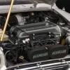
Here is a pic of the alternator:

Sparkie
Posted 29 July 2013 - 03:07 PM
The black box you refer to and in the photo is a Double Relay 12v 40a of the normally open variety, its just a double relay side by side. Have to confess never seen that with any wires coming off the alternator.
Does it click on off in each box when the ignition is switched on/off ? odd one here? I could tell you if I was there with the car but only guessing why its on the alternator circuit
85/86 is the switch circuit and the 87/30 is where you need to follow and see where its connected
Only thing that springs to mind is its used for the daytime running lights (are they still connected) where they are not on if the engines not on and running and a trigger from the alternator to bring the relays in.
I'd convert back to standard alternator wiring, 2 large browns to Batt + on solenoid and the Ind wire to the warning light.
Sorry cant be of anymore help, different if the car was in my W/S in front of me.
Edited by KernowCooper, 29 July 2013 - 03:20 PM.
Mini Mad
Posted 29 July 2013 - 04:33 PM
Up Into Fourth
Posted 29 July 2013 - 05:47 PM
I will chase the wires around now.
The thing with the daylight running is that all the wiring appears to be be factory original.
The car is a German export
Up Into Fourth
Posted 29 July 2013 - 08:15 PM
So I tried to follow the wiring from the double relay, and it basically lead to and form the head lights and not the ignition switch.
I then followed the yellow and brown wire from the ignition switch all the way around the engine and found this...

so running from the small pin on the alternator was this connector....

One side goes of to deal with the day light running and the other is the original ignition warning light (which had come out).
AND then........

Many thanks everyone, i would have been able to track it down other wise.
Tomorrows job tidy all this away again....

Sparkie
Posted 29 July 2013 - 08:44 PM
Had a feeling it was to do with the running lights, satisfying when you fine the fault, its sure makes the standard mini wiring look straight forward when you have mods such as yours.
Up Into Fourth
Posted 29 July 2013 - 08:49 PM
Indeed it has been a bit of a baptism of fire to wiring and electrics for me
Camshaft & Stage Two Head

Posted 30 July 2013 - 04:14 AM
To see how the DRL wiring is done, look up a split charge circuit diagram and substitute the second battery with the DRL lamps and you will be able to understand what is happening. the alternator w/l connection is used to trigger the relay so that the lamps/load is only on when the engine is running. I use this method for the running lamps on the machines at work. It basically prevents battery drain if the load is left switched on accidentally with the engine not running. Wish i had seen this thread sooner, i would have jumped in with the answers for you.


0 members, 1 guests, 0 anonymous users


