Jump to content


Photo
- - - - -

Radius Arm Disaster - Best Way Forward


  • Please log in to reply
28 replies to this topic

#16 mini13

mini13

    Up Into Fourth

  • Members
  • PipPipPipPipPipPipPipPipPip
  • 3,811 posts

Posted 09 August 2013 - 06:05 PM

Is it possible to pull the two big pins out that go through the heelboard subfram mounts? (been a while since I looked at a rear subby).


If so you can leave the troublesome front mounts in place and drop the subby off and take it somewhere to get nuts welded in.


#17 Tamworthbay

Tamworthbay

    Crazy About Mini's

  • Members
  • PipPipPipPipPipPipPipPipPipPip
  • 7,025 posts
  • Name: Clive
  • Location: Tamworth
  • Local Club: A5 minis

Posted 09 August 2013 - 06:10 PM

No, the subframe mounts will have to come out to get it off.

#18 Rog46

Rog46

    Speeding Along Now

  • Noobies
  • PipPipPipPipPip
  • 465 posts
  • Location: Sussex
  • Local Club: NSMOC

Posted 09 August 2013 - 09:08 PM

I've always been advised to use a left handed drill bit (available on eBay) when drilling bolts out, then if it does come loose it comes out!

Re power, have you considered hiring a small generator to give you power for a weekend. It might be easier than getting the subframe off. Or do you know anyone with one? Where are you? (I have one, about 600watts I think, haven't looked for several years, how much power does a MIG take?)

#19 Captain Mainwaring

Captain Mainwaring

    Camshaft & Stage Two Head

  • Banned
  • PipPipPipPipPipPipPipPip
  • 1,712 posts
  • Location: Indonesia
  • Local Club: Surabaya Mini Club

Posted 10 August 2013 - 05:14 AM

Neither ali nor steel rivnuts, hank bushes or any similar devices are strong enough for use on any stressed part of a car. The only safe option is to weld in a nut, properly.


I don't like to be pessimistic, but if you do decide to take the subframe out, please prepare yourself for all the horrors of rotten heelboard ends, captive nuts breaking loose, etc. Been there.....


The big problem comes when the captive nuts break free of the vital inner stiffening bracket, because then you are in to, at the very least, cutting out the rear few inches of the outer sill to enable repairs to be made,and then fitting a sill patch afterwards. Not as difficult as it might seem, but really tedious and annoying.


Give yourself far more time than you think you will need, and use the very best penetrating oil that you can get, several times, over a week or so, to give yourself the best possible chance of an easy outcome.


Good luck!


Rivnuts such as "clufix" are certainly at least as strong as a nut and tack weld- ultimately it's not the strength of the fastener that is in any doubt , but the surrounding steel. 

A 8mm clufix in 1.7mm sheet will take around 1250 kgf to pull it out of unsupported sheet (30mm dia circle around the clufix)

The most important thing to remember with clufix is to ensure they are properly set so they can't spin - easiest way to ensure this is to tack them in two places to the panel. A properly set clufix requires an 8.8 bolt.

Truth is welding anything to sheet doesn't exactly enhance it's strength.


You are right of course, that he will probably find a chamber of horrors behind in anycase, but if the structure is still good, then there are methods of repair that can be used that are at least as strong as the existing without cutting access panels.


#20 sonikk4

sonikk4

    Twisted Paint Polisher!!!

  • Admin
  • PipPipPipPipPipPipPipPipPipPipPip
  • 16,053 posts
  • Name: Neil
  • Location: Oxfordshire

Posted 10 August 2013 - 08:17 AM

There is another option that will require a battery drill and a carbide burr.


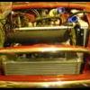
Looking into the companion bin with the lining taken out you will see the wheel arch, the flat plate infront of the wheel arch (close out panel) and the the inner sill stiffener panel.


You will see where the heelboard flange meets the closeout panel rear edge and also where the tang of the inner stiffener sits on the closeout panel.


If you can drill a hole as large as the drill chuck will take (normally 1/2") just behind the closeout panel and drilling through the inner sill stiffener you should be able to make out the captive nuts in the back of the heelboard to inner sill mounting bracket.


Now using the carbide burr enlarge the hole width wise until you can fit in a spanner of the right size for the nut.


Using the technique DILLIGAF mentioned for punching out the broken bolt you should be able to dislodge the old captive nut. Once this is done tape you new nut to the ring end of the spanner and insert into the hole. Using a mate get them to push the new bolt through the trunnion and into the heelboard. Now with a bit of patience you should be able to start the new nut onto the bolt. Tighten fully.


Now hopefully you can get the car back on the road. When the first chance becomes available weld a patch over the hole you have made.


If this has been done obviously you will need to think about cutting a section of the outer sill off to gain access to the back of the heel board to weld in new nuts.


If you have a look at the Project Erm link below towards the end of the thread you will see where i have had to do exactly the very method i have just described. Page 45 item 662.


#21 Captain Mainwaring

Captain Mainwaring

    Camshaft & Stage Two Head

  • Banned
  • PipPipPipPipPipPipPipPip
  • 1,712 posts
  • Location: Indonesia
  • Local Club: Surabaya Mini Club

Posted 10 August 2013 - 08:52 AM

I've always been advised to use a left handed drill bit (available on eBay) when drilling bolts out, then if it does come loose it comes out!

Re power, have you considered hiring a small generator to give you power for a weekend. It might be easier than getting the subframe off. Or do you know anyone with one? Where are you? (I have one, about 600watts I think, haven't looked for several years, how much power does a MIG take?)


Have a think about this for a bit......you're going to try and pull a corroded end back through a nut with a left handed drill....probably about the same as drilling it out with a right handed drill. That may work on a stud in a cast block, but not in something like a broken bolt in a rusty nut.


Running welders on a genset requires a genset well over the rating of the welder because the genset will tend to sag and you'll lose arc voltage before the govenor picks back up.


Edited by Captain Mainwaring, 10 August 2013 - 08:54 AM.


#22 Rog46

Rog46

    Speeding Along Now

  • Noobies
  • PipPipPipPipPip
  • 465 posts
  • Location: Sussex
  • Local Club: NSMOC

Posted 10 August 2013 - 05:11 PM

Yes you're quite right, but it's always good to always use the best method if you can, otherwise you forget when it does make a difference.

Thanks for the info re powering a MIG, I've never had to do it , just a thought.

#23 Tamworthbay

Tamworthbay

    Crazy About Mini's

  • Members
  • PipPipPipPipPipPipPipPipPipPip
  • 7,025 posts
  • Name: Clive
  • Location: Tamworth
  • Local Club: A5 minis

Posted 10 August 2013 - 05:24 PM

We run a mig off a 2kw genny at work. captain is right regarding the output but as the welder is never run at anywhere near its max settings it works fine. Ours is aimed at the cheap end of the pro market and like most will weld very thick metal if required. Because cars are mostly thin metal the welder is never drawing a massive amount of juice. If you were making wrought iron gates it would be a different matter but a 2kw generator has worked fine for all the automotive jobs we have used it for which constitute almost any job you are likely to do on a car. The spot welder however won't work on a genny. We gave it a go in the hope that it would work on its low setting (1+1mm) but the way it draws current trips the generator every time.

#24 humph

humph

    How bad can it Be?

  • TMF+ Member
  • PipPipPipPipPipPipPip
  • 1,101 posts

Posted 13 August 2013 - 01:10 PM

Thanks for the replies so far guys.  I went to the lock up the other day to look at the whole thing with fresh eyes, and felt a bit better about it all. I've still got a single bolt spinning freely; I will have to hire a genny to grind this off. I then looked at the others and decided it was best if I followed a suggestion on here and punched them through leaving nice clean holes. 


I've been thinking about favoured ways forward, and these are as follows:


1) Enlarge the holes slightly and weld in a captive nut from the outside as seen in this link http://www.mig-weldi...ead.php?t=29884. The only minor issue I have here is whether or not there is much strength in the welds once they're ground down.  Should the holes be big enough to leave a small gap around the nut so that there is the opportunity to get more weld through to the nut?


2) The following link is for repair of subframe bolts, but I recon the idea could work here too, http://www.dummett.n...rear_bolts.html. My issue here is all that hammering could deform the location of the nuts, meaning the bracket goes on squiff and the car crabs.


3) This is an amalgamtion of 1 & 2; Make up a plate with the two new nuts welded to it, using the bracket as a template. Open up the existing holes in the subby and plant the plate onto the subby with the nuts protruding through the existing holes.  This planted plate will then be welded all round, and probably plug welded to the subby through a couple of extra holes.  Grind down the welds and hey presto. Big question here is what affect planting a plate on the subby will have on the position of the radius arm? Castor/Camber? Will it really matter? How thick is the material they make subframes out of anyway?


Thoughts appreciated.


#25 DILLIGAF

DILLIGAF

    Up Into Fourth

  • Banned
  • PipPipPipPipPipPipPipPipPip
  • 3,615 posts

Posted 13 August 2013 - 01:30 PM

Just a quick note, the subframe mounting brackets don't go into the the heelboard they attach the radius arm to the subframe.........


#26 A-Cell

A-Cell

    Camshaft & Stage Two Head

  • Members
  • PipPipPipPipPipPipPipPip
  • 1,610 posts
  • Location: Longbridge

Posted 13 August 2013 - 01:59 PM

Humph your item 2 heelboard repair would not be strong enough. The captive weld nuts are on another reinforcing plate inside the heelboard. Just welding to the face of the heelboard would not be strong enough.
The subframe needs bolting through the heelboard and the reinforcement.
Opening the closed section is the only viable option, either via Sonnik's route from insid the companion box or through the outer sill.

#27 humph

humph

    How bad can it Be?

  • TMF+ Member
  • PipPipPipPipPipPipPip
  • 1,101 posts

Posted 13 August 2013 - 04:08 PM

Just a quick note, the subframe mounting brackets don't go into the the heelboard they attach the radius arm to the subframe.........


Humph your item 2 heelboard repair would not be strong enough. The captive weld nuts are on another reinforcing plate inside the heelboard. Just welding to the face of the heelboard would not be strong enough.
The subframe needs bolting through the heelboard and the reinforcement.
Opening the closed section is the only viable option, either via Sonnik's route from insid the companion box or through the outer sill.


Cheers, good points, I agree, but I'm not intending on using it for subframe mounts.  The link in option 2 is for example purposes only, it relates to the subframe mounts, and not the radius arm bolts I'm trying to fix. My thoughts were along the lines of whether this solution can be utilised/modified in the location I need (radius arm brackets). 


Edited by humph, 13 August 2013 - 04:13 PM.


#28 Cooperman

Cooperman

    Uncle Cooperman, Voted Mr TMF 2011

  • TMF+ Member
  • PipPipPipPipPipPipPipPipPipPipPip
  • 23,309 posts
  • Location: Cambs.
  • Local Club: MCR, HAMOC, Chelmsford M.C.

Posted 13 August 2013 - 05:14 PM

The only proper & safe way to repair the captive nuts inside the heel-board is to cut a rectangular hole in the sill about 3" x 4" to give proper access. Then make up a new nut plate, weld it in place after bolting the sub-frame trunnions in place firmly then weld a repair plate onto the sill flush with the sill, grind back, skim with a very light surface of filler, prime & paint.
It's about a 2 hour job plus time for painting the sill.

#29 A-Cell

A-Cell

    Camshaft & Stage Two Head

  • Members
  • PipPipPipPipPipPipPipPip
  • 1,610 posts
  • Location: Longbridge

Posted 13 August 2013 - 05:36 PM

Just a quick note, the subframe mounting brackets don't go into the the heelboard they attach the radius arm to the subframe.........


Humph your item 2 heelboard repair would not be strong enough. The captive weld nuts are on another reinforcing plate inside the heelboard. Just welding to the face of the heelboard would not be strong enough.
The subframe needs bolting through the heelboard and the reinforcement.
Opening the closed section is the only viable option, either via Sonnik's route from insid the companion box or through the outer sill.


Cheers, good points, I agree, but I'm not intending on using it for subframe mounts.  The link in option 2 is for example purposes only, it relates to the subframe mounts, and not the radius arm bolts I'm trying to fix. My thoughts were along the lines of whether this solution can be utilised/modified in the location I need (radius arm brackets).

Ok got you. I reckon, done well and diligently, that would work. This would be for 2 out of 4 fixings, as the other 2 are not in a box section.


0 user(s) are reading this topic

0 members, 0 guests, 0 anonymous users