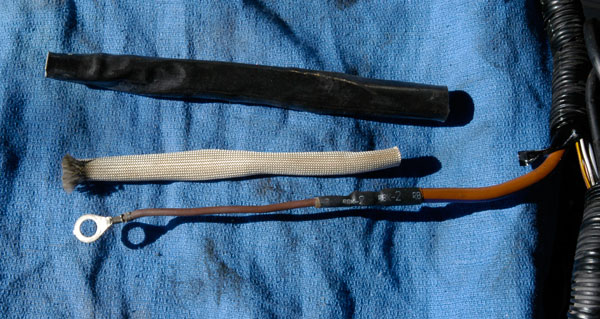
As this crops up a lot here is a few facts on the Fusible Links fitted in the Alternator to Solenoid wiring.
The Fusible links are part of the vehicles wiring loom and not available in the the retail market
This is what a fusible link looks like and its location is on the end of the Alternators large brown wire to the starter solenoid.
The outer is marked Hypalon’ which is a heat resistant insulation
They were used on the later Minis with a ECU, SPI/MPI Models as a means of protection of overcharging to protect the ECS.
HOW TO TEST THE FUSIBLE LINK/S
Disconnect the Battery
Remove the plug from the rear of the Alternator, or remove the thick brown wire from the stud on the rear of the Alternator, depending which model Alternator you have
Turn a Multimeter onto ohms for Continuity testing (icon that looks like a sound wave or a Wi-Fi connection indicator.)
Touch the RED/BLACK probes together and the meter should read 0.00
Now place one of the probes on the removed terminal from the Alternator and the other probe onto the connection of the starter solenoid where the Alternator connect to
If it again reads 0.00 or close to then there is a circuit through the fusible links
If it reads infinity on the meter then there is NO CIRCUIT and the links are blown
As the Fusible links are hard to get in the UK lots of vehicles have been modified with the links cut out and 50 amp Brown wiring soldered and shrink rapped and the connection remade onto the solenoid.
Obviously the leaves the Alternator to the main battery supply and a step backwards from the original wiring by Rover. I like others have done the mod to return the Alternator Cables back to the earlier spec of non-SPI/MPI cars without trouble.
If your not happy then you can modify the wiring to accept a MIDI Fuses and shrink wrap
The standard Fusible link wires are both 22 strand (0.001mm2 per strand) which unwrapped will melt in about 10s under a load of 85-90amps so wrapped will increase the heat so this will be slightly quicker.
The midi fuses are listed with a amperage, and what you need to remember this is NOT THE BLOW RATING BUT THE CONTINUOUS CURRENT.
IF YOU FIT A MIDI FUSE OF 60a THE BLOW RATING IS DOUBLE AT 120a -THIS APPLIES TO ALL MIDI FUSES
Therefore on the SPI/MPI with the 70a alternator fittted you can use a Yellow 80a Midi.

Alternator cabling is normally 3/4.4mm Thin Wall Cable x 2
Or on Vehicles with higher output alternators 6.0mm 84/0.30mm Thin Wall Cable
So the fusible link will provide up to 80a load and 160a blow.
This obviously requires some level of soldering skill and ensure the links are suitably covered with shrink wrap and away from any part of the engine which could chafe the insulation
OBVIOUSLY YOU NEED TO FIND OUT WHAT CAUSED THE FUSIBLE LINKS TO BURN OUT !
Edited by KernowCooper, 27 June 2015 - 09:13 PM.


