Jump to content


Photo
- - - - -

2 Types Of Smiths Rev Counter


  • Please log in to reply
29 replies to this topic

#16 Indigo

Indigo

    On The Road

  • Noobies
  • PipPip
  • 42 posts
  • Location: South Australia

Posted 24 September 2020 - 02:17 AM

I have both an RVI and RVC in the Twini.

Engines are A+ with the standard electronic ignition (little module on side of distributor)

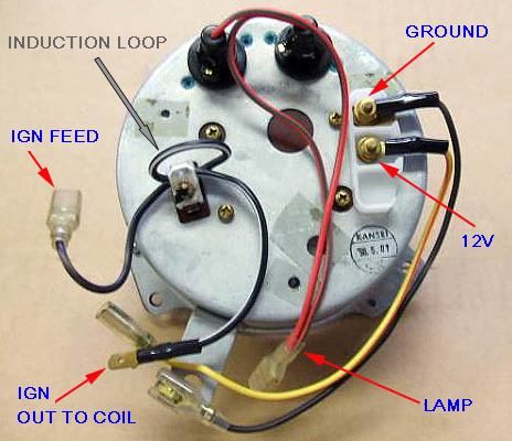
One Tacho on the rear engine, the other on the front.

Both are Smiths tachos, look similar from the front but the rears are obviousley different, one having the wire loop, the other three spade terminals.

Both Tachos read the same throughout the range (to around 6,500 RMP) unless I have wheel spin, slipping clutch or only one engine running (when starting up).

The RVI has more bounce or lag in the needle when revs change rapidly. 


#17 1963MKI

1963MKI

    Mini Mad

  • TMF+ Member
  • PipPipPipPip
  • 163 posts

Posted 24 September 2020 - 04:41 PM

Just think:40 years ago it may only have had ten minutes to live.Seriously any capacitors in it could have failed as older ones are prone to doing,free to take a look,Enjoy faulting it,Steve..


yea perhaps you're right. Has anyone had any sucess buying repair kits ?


#18 1963MKI

1963MKI

    Mini Mad

  • TMF+ Member
  • PipPipPipPip
  • 163 posts

Posted 24 September 2020 - 06:40 PM

Im doubly stumped now. My car is just on the road after a rebuild. So I only now got around to adjusting the voltage regulator. Adjusted it, the tach worked again for 5 minutes. Now nothing again.

#19 Spider

Spider

    Moved Into The Garage

  • Admin
  • PipPipPipPipPipPipPipPipPipPipPip
  • 13,936 posts
  • Location: NSW
  • Local Club: South Australian Moke Club

Posted 24 September 2020 - 08:16 PM

It's hard to say for sure what the issue is there, but in regards to repair kits, I have a recollection the Spiyda Design has (had?) something like that for Smith's Tachos.


#20 1963MKI

1963MKI

    Mini Mad

  • TMF+ Member
  • PipPipPipPip
  • 163 posts

Posted 08 December 2020 - 10:19 PM

Ive just bought a new transistor and capacitor for the tacho. Hopefully that should fix the issue. However, the transistor didn't come with a data sheet. There are three colour coded legs on it, purple green and white. Its a mullard GET114. Does anyone know which leg is the base, emmitter and collector ?


#21 Edington

Edington

    Mini Mad

  • Noobies
  • PipPipPipPip
  • 108 posts
  • Location: North somerset

Posted 13 February 2021 - 10:25 AM

Attached File  Smiths RV1 Tacho.jpg   46.26K   0 downloadsDoes anyone have the wire connection details for a Smiths RV1 Tacho? Apart from the obvious panel light and earth I'm interested in the Green (I think this is 12V supply) but not sure about the white/Black and white/yellow.


#22 Chris1275gt

Chris1275gt

    One Carb Or Two?

  • TMF+ Member
  • PipPipPipPipPipPipPip
  • 798 posts
  • Location: Reading

Posted 13 February 2021 - 02:50 PM


I'm almost positive the w/y and w/b are connected in series to the coil from the ignition and the green is the 12v supply.

#23 Ethel

Ethel

    ..is NOT a girl!

  • TMF Team
  • PipPipPipPipPipPipPipPipPipPipPip
  • 25,419 posts
  • Local Club: none

Posted 13 February 2021 - 03:17 PM

White/black from ignition live, white/yellow to coil +ve. Colours aren't standard but it identifies the connections.


#24 Edington

Edington

    Mini Mad

  • Noobies
  • PipPipPipPip
  • 108 posts
  • Location: North somerset

Posted 13 February 2021 - 04:43 PM

Sorry if I sound a bit thick but I've read numerous posts on the RV1 so far relating to the terms 'Tacho in or Ignition supply in' and Tacho out or Ignition supply out'.


So for clarification the white/yellow or 'Tacho out' connects to the +VE terminal on the coil (as it's a negative earth system).


It's the 'Tacho in' that I'm struggling with i.e. the White/black wire on my photo above. So is the existing White cable removed from the +VE terminal of the coil which is then connected to the White/black 'Tacho in'?


#25 Ethel

Ethel

    ..is NOT a girl!

  • TMF Team
  • PipPipPipPipPipPipPipPipPipPipPip
  • 25,419 posts
  • Local Club: none

Posted 13 February 2021 - 04:59 PM

It's RV "i", for induction. It senses when the current flowing to the coil is switched by the points. The ignition wiring just goes in on one terminal  & out on the other. There are versions of RVI tacho that just have the ignition wire held in a coil externally.


So, yes replace the white on the coil with an ignition feed via the Tacho.


1c29471818626a08cd9d0446ca3dc210eab0477a


#26 Spider

Spider

    Moved Into The Garage

  • Admin
  • PipPipPipPipPipPipPipPipPipPipPip
  • 13,936 posts
  • Location: NSW
  • Local Club: South Australian Moke Club

Posted 13 February 2021 - 05:20 PM

Sorry if I sound a bit thick but I've read numerous posts on the RV1 so far relating to the terms 'Tacho in or Ignition supply in' and Tacho out or Ignition supply out'.


As far as the Ignition wiring 'loop' goes (Either a loop of wire that feeds the Distributor or a wire in, wire out type), it won't damage anything if these are connected wrong. If wrong, it won't work, swap them over and it should work.


#27 Chris1275gt

Chris1275gt

    One Carb Or Two?

  • TMF+ Member
  • PipPipPipPipPipPipPip
  • 798 posts
  • Location: Reading

Posted 13 February 2021 - 05:20 PM

for a points system

Attached Files


#28 Edington

Edington

    Mini Mad

  • Noobies
  • PipPipPipPip
  • 108 posts
  • Location: North somerset

Posted 15 February 2021 - 10:00 PM

Many thanks guys. All wired in and works a treat  :shifty:


#29 Tornado99

Tornado99

    One Carb Or Two?

  • Members
  • PipPipPipPipPipPipPip
  • 750 posts
  • Location: Vancouver

Posted 16 February 2021 - 12:34 AM

And for any future questions on these tacho's, I'll link to the excellent Gentlemen's Guide to Smiths Tachometers:


https://www.triumphc...chometers-1.pdf


#30 1963MKI

1963MKI

    Mini Mad

  • TMF+ Member
  • PipPipPipPip
  • 163 posts

Posted 25 February 2021 - 09:37 PM

just to update on my tacho. I fit it to the car after it sitting on the shelf for 30/40 years. Worked perfectly for 5 minutes. then nothing. 


So i started by replacing the capacitor, again it worked for 5 minutes then nothing. I was really stumped at this point so I changed the transistor and the variable resistor. Again nothing. Luckily my father is a communications engineer so he had a signal generator and bench power supply. So we tried that in every way shape and from and couldnt get anything out of it. At this point I had basically run out of things to replace that might be making it faulty. So, my grandfather gave me his oscilloscope. Turns out we had been injecting the wrong type of signal from the signal generator, our pulses were in the wrong direction. As soon as we figured this out with the scope we got the correct signal into it. It worked perfectly.


My dad had a good idea how to calibrate it on the car which we used to great effect. A blob of tipex on the timing mark on the crank pulley and by hooking an LED to the signal generator and using the stroboscopic effect at the desired frequency. So we would set the signal generator to a certain frequency, and someone would pull the throttle until they get strobing, then the other person would adjust the tacho variable resistor to dial it back to the rpm it should read at that frequency. Worked very well.


0 user(s) are reading this topic

0 members, 0 guests, 0 anonymous users