Jump to content


Photo

Spi Air Intake Sensor Fault


  • Please log in to reply
23 replies to this topic

#1 connorj

connorj

    Learner Driver

  • Noobies
  • PipPip
  • 11 posts
  • Location: Gosport

Posted 20 July 2014 - 02:01 PM

Hi guys,


First off this forum is brilliant and has already helped me a lot with my mini, especially Sporcket's stuff, so thanks for that.


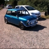
I have a 1995 1275cc SPI mini sidewalk. I've had it for about 3 months and since I bought it has had a problem with uneven running and poor cold start/idling and stalling.


To start off with the revs used to run away when you stopped at the lights and it idled way too fast. Easy, replaced all the shot vacuum hoses with silicone hoses. With that sorted it runs okay when up to temperature but you have to keep your foot lightly on the accelerator for a few minutes, effectively acting like a choke, when starting from cold otherwise it splutters at about 500-650 rpm before eventually stalling.


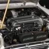
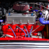
After renewing the plugs and seeing the old ones were running lean, I plugged it into a diagnostics machine and it came up with air intake sensor cct error. It read ambient temp at 200 degs and air intake at 35 degs. As I understand it from what I've read, this is a preset value when a sensor fails and the ecu goes into "limp home" mode. At this point I should mention I have a k&n filter with the air intake sensor fitted correctly and the advance/reatard blanked, this was done before I bought the car. So I bought a replacement air intake sensor and still have the same problem.


I am about to trace and test all the wiring in depth but initial reading at the terminals of the air intake sensor were good.


I have run out of things to try and the only other logical reason I could think of is maybe a faulty ECU, which seems unlikely from what's been said.


Also I wonder if resetting the ecu would help but i've read this can only properly be done via a dealer's diagnostics machine.


Thanks in advance for your help!


#2 minisilverbullet

minisilverbullet

    Up Into Fourth

  • TMF+ Member
  • PipPipPipPipPipPipPipPipPip
  • 3,799 posts
  • Name: Craig
  • Location: Sweden

Posted 20 July 2014 - 02:28 PM

I had a bit of a baptism of fire with the same issue just last week. I can share with you what i learned.....


Do you know the sensor is good? you can place a multimeter of the sensor and set it to ohm, them somehow gently heat the sensor up ( held it about 25 cm above candle, but be careful) the resistance reading should decrease as the sensor gets hot. 


Next, with the ignition on, I would check for a 5v supply across the terminal of the sensor. just remove the sensor and set the multi meter to 9v and place both multimeter "pins" across the sensor terminal, you should se approx 5v. 


I didn't had a 5v supply to the sensor, so I (we) suspect the ECU. the ECU has been sent away to be tested. 


let us know how you get on. 


#3 connorj

connorj

    Learner Driver

  • Noobies
  • PipPip
  • 11 posts
  • Location: Gosport

Posted 20 July 2014 - 02:58 PM

Thanks for the quick reply!


The air intake temperature sensor was brand new but I put it in the fridge for a few minutes and the resistance went from 5k to around 6k which is right because it's inversely proportional. I then tested across the terminals and had 5k resistance. Then after a lot of wiggling the multimeter terminals got 5v across the sensor mount terminals. I suppose this means the ecu is supplying the correct voltage and there are no breaks in the wire? Which confuses me even more. Runs the same with the sensor in or out so I think it is receiving the information but not using it and instead putting it at 35 and putting the car in limp home mode.


Maybe this points to needing to reset the ecu? I know it learns and stores the settings but you'd think once the error was fixed it would automatically relearn the corrected settings.


That is a wicked mini you have by the way.


Edited by connorj, 20 July 2014 - 02:58 PM.


#4 minisilverbullet

minisilverbullet

    Up Into Fourth

  • TMF+ Member
  • PipPipPipPipPipPipPipPipPip
  • 3,799 posts
  • Name: Craig
  • Location: Sweden

Posted 20 July 2014 - 03:17 PM

Thanks for the quick reply!


The air intake temperature sensor was brand new but I put it in the fridge for a few minutes and the resistance went from 5k to around 6k which is right because it's inversely proportional. I then tested across the terminals and had 5k resistance. Then after a lot of wiggling the multimeter terminals got 5v across the sensor mount terminals. I suppose this means the ecu is supplying the correct voltage and there are no breaks in the wire? Which confuses me even more. Runs the same with the sensor in or out so I think it is receiving the information but not using it and instead putting it at 35 and putting the car in limp home mode.


Maybe this points to needing to reset the ecu? I know it learns and stores the settings but you'd think once the error was fixed it would automatically relearn the corrected settings.


That is a wicked mini you have by the way.


Well thats 5v more than i got! 


I wonder if it the car is in limp mode for another reason? can you delete the fault code? does it retur?


cheers its a great car ..... when its working. 


#5 connorj

connorj

    Learner Driver

  • Noobies
  • PipPip
  • 11 posts
  • Location: Gosport

Posted 20 July 2014 - 03:21 PM

Can't clear the fault code, it returns immediately. I might try playing around with using a jumper wire to the earth pin to make sure it's getting a good earth.


Just read your thread and it is by far the most helpful and in depth on this issue. Sounds exactly like mine except you found the problem haha. I guess if it's not a supply issue it could be an earth issue.


#6 minisilverbullet

minisilverbullet

    Up Into Fourth

  • TMF+ Member
  • PipPipPipPipPipPipPipPipPip
  • 3,799 posts
  • Name: Craig
  • Location: Sweden

Posted 20 July 2014 - 03:28 PM

well i hope i found the issue. 


Seems that you are of to a running start, i was a bit over my head at times. 


Do you know what the CCT part of the fault code means. A quick google suggests short circuit or ground fault. 


#7 FlyingScot

FlyingScot

    Up Into Fourth

  • TMF Team
  • PipPipPipPipPipPipPipPipPip
  • 2,664 posts
  • Location: Inverclyde Scotland
  • Local Club: Mini Cooper Register

Posted 20 July 2014 - 10:13 PM

Resetting the ECU won't help if the fault is active.
(You can reset the ECU with the Crypton ACT system or Testbook). Fault should clear if problem corrected.
If the fault returns after clearing you could have a wiring fault (more likely than a sensor fault IMHO)
Your tests confirm ECU voltage to sensor, so check earth back to ECU.
Ambient temp isn't used on a mini (hence 200 degrees)' no advance retard on these (timing controlled by MEMS ECU).
The vacuum pipe plugged when K&N used is the one to the air filter (comes off inlet manifold ).

What diagnostic system are you using?

FS

#8 connorj

connorj

    Learner Driver

  • Noobies
  • PipPip
  • 11 posts
  • Location: Gosport

Posted 21 July 2014 - 03:07 PM

Okay so to update:


After extensive testing and retesting several times to be sure here are the results:

pin 16 g/bk wire 0v

p/bk earth wire to air intake temp sensor is 0v

In other words I was wrong abut there being 5v at the supply to the air temp sensor. The first reading I took showed 5v but then dissapeared. I'm guessing it had become charged because of me messing around with the multimeter then discharged as soon as it was read. This is exactly the same as this post from minisilverbullet: 


http://www.theminiforum.co.uk/forums/topic/286450-help-decipher-these-fault-codes-live-data-spi/page-4


However, seeing as there is 5v at the tps, would it be possible/logical/not a really stupid thing to do, to use the 5v feed up the yellow and purple wire to the tps and bridge it across to the green and black wire for the air intake sensor? or using another 5v feed?


The other thing i noticed was the green/black supply to the air sensor (pin 16 effectively) was earthed. Does this mean it has short circuited with the pink/black? Possibly inside the sensor mount? I am tempted to cut off the mount and measure the wires then resolder on the mount on. If it was short circuited in the mount this would show.


Trying to be really careful because I know it's all too easy to balls up the ecu if you start messing around with the wiring.


Thoughts would be appreciated!


P.S Flyingscot, I have a sykes diagnotics tool with rover pod 2


#9 minisilverbullet

minisilverbullet

    Up Into Fourth

  • TMF+ Member
  • PipPipPipPipPipPipPipPipPip
  • 3,799 posts
  • Name: Craig
  • Location: Sweden

Posted 21 July 2014 - 03:13 PM

Okay so to update:


After extensive testing and retesting several times to be sure here are the results:

pin 16 g/bk wire 0v

p/bk earth wire to air intake temp sensor is 0v

In other words I was wrong abut there being 5v at the supply to the air temp sensor. The first reading I took showed 5v but then dissapeared. I'm guessing it had become charged because of me messing around with the multimeter then discharged as soon as it was read. This is exactly the same as this post from minisilverbullet: 


http://www.theminiforum.co.uk/forums/topic/286450-help-decipher-these-fault-codes-live-data-spi/page-4


However, seeing as there is 5v at the tps, would it be possible/logical/not a really stupid thing to do, to use the 5v feed up the yellow and purple wire to the tps and bridge it across to the green and black wire for the air intake sensor? or using another 5v feed?


The other thing i noticed was the green/black supply to the air sensor (pin 16 effectively) was earthed. Does this mean it has short circuited with the pink/black? Possibly inside the sensor mount? I am tempted to cut off the mount and measure the wires then resolder on the mount on. If it was short circuited in the mount this would show.


Trying to be really careful because I know it's all too easy to balls up the ecu if you start messing around with the wiring.


Thoughts would be appreciated!


P.S Flyingscot, I have a sykes diagnotics tool with rover pod 2

wow! exactly the same issue i had just last week. 


I will let you know how my ecu test/ diagnosis go regarding the missing 5v supply. 


#10 connorj

connorj

    Learner Driver

  • Noobies
  • PipPip
  • 11 posts
  • Location: Gosport

Posted 21 July 2014 - 03:37 PM

Also just tested the wires and it's not a short. when read between ground and supply it is an open circuit because the sensor wasn't in, put sensor in and its got 2-3k resistance so as it should be. Same as the coolant sensor wires and tps wires. When the ignition is turned on the tps and coolant both go to short circuit as I guess you're effectively earthing the air temp sensor wire from pin 16 still 2-3k resistance.


I guess all this means it can only be a fault within the ECU and not supplying the air temp sensor with 5v. Think I will try use the 5v from the tps wire and see what happens.


Thanks silverbullet, I would be keen to find out if they fixed yours, and what the financial damage will be!


Edited by connorj, 21 July 2014 - 03:38 PM.


#11 xrocketengineer

xrocketengineer

    Rocket Man

  • Members
  • PipPipPipPipPipPipPipPip
  • 1,637 posts
  • Location: Florida, USA

Posted 21 July 2014 - 04:10 PM

Also just tested the wires and it's not a short. when read between ground and supply it is an open circuit because the sensor wasn't in, put sensor in and its got 2-3k resistance so as it should be. Same as the coolant sensor wires and tps wires. When the ignition is turned on the tps and coolant both go to short circuit as I guess you're effectively earthing the air temp sensor wire from pin 16 still 2-3k resistance.


I guess all this means it can only be a fault within the ECU and not supplying the air temp sensor with 5v. Think I will try use the 5v from the tps wire and see what happens.


Thanks silverbullet, I would be keen to find out if they fixed yours, and what the financial damage will be!

I don't believe that will work. My interpretation of the circuit is that the ECU has an internal 5VDC source that is connected internally to a resistor. When no sensor is connected, it is possible to read the 5 VDC at pin 16. However, when the sensor is connected, then there is a current flowing from pin16 through the sensor to ground. The voltage Internal to the ECU (and at the sensor) is no longer 5 VDC but something less that varies in proportion with the resistance of the sensor. The ECU measures that changing voltage and makes the correction to the fuelling accordingly. So an externally supplied voltage might not work. I am pretty sure FlyingScot's expertise will be of use here.   


#12 dbcool20

dbcool20

    Stage One Kit Fitted

  • Noobies
  • PipPipPip
  • 91 posts

Posted 21 July 2014 - 08:04 PM

As said ^^ really doubt it will work this way using another 5v feed from somewhere.

You mentioned you had 5v at the IAT connector in the beginning, then nothing anymore. could it be a damaged wire or corroded pin with a bad connection giving you voltage only sometimes maybe? 


#13 FlyingScot

FlyingScot

    Up Into Fourth

  • TMF Team
  • PipPipPipPipPipPipPipPipPip
  • 2,664 posts
  • Location: Inverclyde Scotland
  • Local Club: Mini Cooper Register

Posted 21 July 2014 - 08:34 PM

Yes its an internal 5V supply from the MEMS ECU. Do not use a supply from else where please!

Xrocketengineer I would agree with your understanding, the sensors are negative coefficient "resistors" and only a very small sense current is passed the voltage being read by the ECU as the factor which effects the air density.

I am interested that both of you are using Rover Pod 2 with the ACR/2/4 this Is NOT designed for SPI, I was of the opinion previously that this wasn't a problem bit it seems strange that two people with problems are using the wrong pod. Mini SPI needs Rover Pod 1 or Pod 3, 4 5 etc.

I had an issue with a K series mini conversion last week where there was no TPS voltage, turned out it was several issues with poor wiring including supply to the MEMS unit.... and duff earths. 


FS


#14 connorj

connorj

    Learner Driver

  • Noobies
  • PipPip
  • 11 posts
  • Location: Gosport

Posted 21 July 2014 - 08:47 PM

Yes its an internal 5V supply from the MEMS ECU. Do not use a supply from else where please!

Xrocketengineer I would agree with your understanding, the sensors are negative coefficient "resistors" and only a very small sense current is passed the voltage being read by the ECU as the factor which effects the air density.

I am interested that both of you are using Rover Pod 2 with the ACR/2/4 this Is NOT designed for SPI, I was of the opinion previously that this wasn't a problem bit it seems strange that two people with problems are using the wrong pod. Mini SPI needs Rover Pod 1 or Pod 3, 4 5 etc.

I had an issue with a K series mini conversion last week where there was no TPS voltage, turned out it was several issues with poor wiring including supply to the MEMS unit.... and duff earths. 


FS

I have traced the problem back to the ECU. I have checked the pins, wires, and every connector and terminal and there is continuity in the wires just no voltage. I think, like minisilverbullet, I will have to send the ecu off to be repaired. I also visually inspected the ecu circuit board and there are no burns, blows or visible damage. With the joints in the ecu being too small and complicated to test plus the likelihood of further damaging the ecu, I will have to send it away. Also I did try the external voltage and it cleared the error but put the air temp at 200 degs obviously because it wasn't the right supply. Didn't damage anything but at least it is definitely the lack of power causing the fault and not a short or something else. Will let you guys know the result of it being tested. Thanks a lot for all your help! 


#15 connorj

connorj

    Learner Driver

  • Noobies
  • PipPip
  • 11 posts
  • Location: Gosport

Posted 21 July 2014 - 08:51 PM

FlyingScot, do you think it's possible it could be a power supply issue to the mems unit that is the cause? How would you know which supply wires to the mems effect which sensor outputs without a wiring diagram? Also all the earths are good, checked them many times. 


Edited by connorj, 21 July 2014 - 08:51 PM.


1 user(s) are reading this topic

0 members, 1 guests, 0 anonymous users