Thanks screech!
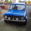
I'm using the Mini daily and I'm just loving the SPi set up - never going back to carbs if I can help it. I'm working on ECU version 2 - PCBs for it arrived today and I'm building one at the moment. This should give me multiport injection and programmed ignition - but its not going in the Mini though.
Be happy to answer any questions - if I can!
That sounds perfect! I've been contemplating injection for a long time now. I'm not expecting power, but cold starts and drivability is what I'm looking for.
What's you multipoint one going to be used on, a proper engine?
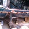
The first question I've got on the unit are what sensors are what...
I've figured out the TPS and idle stepper motor, I'm guessing the one on the right inlet tract is the air inlet temp?
And there's one right underneath in the middle, doesn't look like a removable one, just got 1 space terminal sticking out..?
Cheers
Hi screech
The multipoint is going into a TR7 over the winter 
Hope this answers your questions:
The Air Temp sensor is in the air filter box. I can't say much more about this as I've never used it. I use an LM35 IC for air temp.
Underneath the manifold you've got the coolant temp sensor and the heater. I leave the heater on (connected to the ignition on circuit) and haven't attempted anything fancy. It only draws just over 1 amp so its not a great overhead. The coolant temperature sensor is shown on the left. I had to remove the coolant pipe to clear the tubular manifold, so I can't use this sensor at the moment. I use the coolant temp sensor on the head instead.

You've probably sussed this already but at the back there's two vacuum pipes -the one on the right goes through a vapour trap and then to the ECU MAP sensor. The red one goes to the air box and activates the hot air control flap (I believe its called a "Thermatic Valve"). I've blanked this off.
You can feed the dizzy vacuum advance by inserting a T piece in the MAP pipe, if required.

I've also blanked off the three connections at the front of the TBI. I haven't a clue what the two connections are at the base but I've connected them together.

Hope this helps!