I was struggling to get my new to me 67 morris mini deluxe running after tuning up the engine. Checked and double checked all the wiring and it wouldnt run. Finally I played with the HT lead wiring and found that the engine starts and runs like normal with the plugs firing in 4-2-1-3.
In reading it seems that perhaps the last owner maybe set the timing off of the #4 cylinder at tdc or the #1 cylinder at. Tdc but on the exhaust stroke instead of compression.
My question is will this effect anything, or will it be fine and run properly like this. The engine sounds like it runs fine, but having mever driven another classic mini, I have nothing to compare to.
Thanks.


998Cc Only Runs With 4-2-1-3 Firing Order
Started by
Darthteddy
, Sep 29 2015 04:28 AM
8 replies to this topic
#1

Darthteddy
-
- Noobies
-

- 21 posts
Learner Driver
- Location: Ontario, California
Posted 29 September 2015 - 04:28 AM
#2
Spider
-

- Admin
-
- 15,676 posts
Moved Into The Garage
- Location: NSW
- Local Club: South Australian Moke Club
Posted 29 September 2015 - 05:07 AM
Nope, it won't worry or upset anything.
If you shuffle through the numbers, you'll see that you do still have a firing order of 1-3-4-2;-
What you say you have now is 4-2-1-3
Next 'sequence' is 3-4-2-1
Next again is 1-3-4-2
(hope that makes sense), so it's a mater of perspective, as to which cylinder you want to start counting from.
#3
timmy850
-

- Members
-
- 3,557 posts
Up Into Fourth
- Location: NSW, Australia
- Local Club: MITG
Posted 29 September 2015 - 05:41 AM
You might have the distributor in 180 degrees out? I assume you are counting the cylinders from the correct end (the fan end) and thinking the distributor rotates the correct direction (counter clockwise)?
Try this photo
http://new.minimania...8A56D83229B.jpg
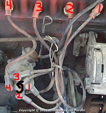
Link: http://new.minimania...plug_wire_order
Edited by timmy850, 29 September 2015 - 05:44 AM.
#4
hhhh
-
- Members
-
- 422 posts
Speeding Along Now
Posted 29 September 2015 - 04:11 PM
If your wires don't match the above picture, but are 180 degrees out, then the distributor drive spindle has been installed 180 degrees out. It has a slot that is offset which needs to be aligned at 2 o'clock and 8 o'clock with the larger half up at number 1 TDC compression. It's easy enough to change by pulling the dizzy, its clamp, and withdrawing the spindle, but you'll have to re-time the ignition after. May as well leave it as is as it won't do any harm except confuse someone not expecting it.
#5
Darthteddy
-
- Noobies
-
- 21 posts
Learner Driver
- Location: Ontario, California
Posted 30 September 2015 - 04:23 AM
Finally got the car out for a drive today. Ran absolutely terribly. Im assuming that the timing is way out. I guess I'm going to fix it so that everything is in the proper position while I'm at it.
Is it a matter of putting cylinder 1 at TDC on compression stroke, then pulling the dizzy off, rotating the spindle around, then reassemble?
And as far as timing goes, my engine does not have timing marks on the timing gear cover. Can I just make one when I have it at top dead center and another on the timing cover, then use that as my reference point? I tried looking through the clutch cover, but didn't have much luck finding any marks.
Thanks
#6
Spider
-
- Admin
-
- 15,676 posts
Moved Into The Garage
- Location: NSW
- Local Club: South Australian Moke Club
Posted 30 September 2015 - 07:41 AM
More or less, but a bit more to it.
Before you do this change the orientation of the distributor drive, check if in fact it is incorrect first. Turn the engine over until you have No. 1 Cylinder at TDC with both valves closed (firing position) then look at the rotor button on the dissy, it should be pointing roughly to 2 o'clock.
If it's not right and you'd like to correct it (and not the end of the world if it's out), keep the engine on No. 1 TDC as above, then after removing the distributor you need to remove the distributor sleeve (if pre A+ which yours should be), that's just a case of removing the distributor clamp and then removing the 1/4" UNF Bolt in the sleave, you can see the bolt head here (a 7/16" Socket is needed)

Then find a 5/16" x 4" bolt and that will screw in to the distributor drive as seen here (though the sleeve is still in place in this photo);

CAUTION: It is possible to drop the drive inside the engine, then what started out as a small 5 minute job will turn in to an all day affair. After fitting the bolt, a bit a string tied off to something else and the bolt may not be a bad idea. I'd suggest not trying with anything less than a bolt 4" long, otherwise there is a good chance you'll drop it in. Note that the gears inside are helical so as you pull it out, it will spin a bit and that's normal.
Then refit it so that it ends up thus

It may end up taking a couple of goes so that it does end up this way due to the helical gears and it does take a bit of mucking about to get it to slip in as the crank will be orientated in a less than ideal position making it not quite slip straight back in.
Then reassemble and re-jig your leads.
The timing marks on your model will be on the flywheel and you'll really need a mirror to see them properly. I'd suggest turning the engine over by hand to TDC where the marks will be, then spraying some white paint in the timing cover inspection hole to make the timing marks easier to see.

Edited by Moke Spider, 30 September 2015 - 07:43 AM.
#7
hhhh
-
- Members
-
- 422 posts
Speeding Along Now
Posted 30 September 2015 - 02:04 PM
I love the way the Haynes (don't they make underwear too?) manual advises you to use a lifter cover bolt to hold the drive spindle. As if that's a convenient bolt to pull, and it's way too short to be safe as noted above.
#8
Spider
-
- Admin
-
- 15,676 posts
Moved Into The Garage
- Location: NSW
- Local Club: South Australian Moke Club
Posted 30 September 2015 - 09:09 PM
I love the way the Haynes (don't they make underwear too?) manual advises you to use a lifter cover bolt to hold the drive spindle. As if that's a convenient bolt to pull, and it's way too short to be safe as noted above.
Yeah, the bolt I use is the one of the ones that fixes the Engine Mount Bracket to the gearbox, but I'm not sure these were used in later days in the UK?
P/N HBZ534 http://www.minispare...ck to catalogue
#9
Darthteddy
-
- Noobies
-
- 21 posts
Learner Driver
- Location: Ontario, California
Posted 01 October 2015 - 02:30 AM
Ahhh very good instructions. Before it was about as clear as mud!
Got the drive flipped around. It was actually about 90* off. I got it back together and started timing the engine. Its a little better now, but still has absolutely no power. Need to look deeper into whats causing the loss of power.
Got the drive flipped around. It was actually about 90* off. I got it back together and started timing the engine. Its a little better now, but still has absolutely no power. Need to look deeper into whats causing the loss of power.


0 user(s) are reading this topic
0 members, 0 guests, 0 anonymous users


