Jump to content


Photo

My Classic Mini Cad Work


  • Please log in to reply
37 replies to this topic

#1 Mini 360

Mini 360

    Up Into Fourth

  • Members
  • PipPipPipPipPipPipPipPipPip
  • 4,933 posts
  • Location: Aberdeenshire
  • Local Club: Independent

Posted 09 September 2016 - 04:28 PM

In my lunch hours at work I am gradually working away on some classic Mini CAD work.  My plan is to use it for my upcoming HND graded unit project so I'm trying to make it as accurate as possible.  It helps that I work in engineering and have an inspection department at my disposal though :lol:


Anyway, I'm starting this thread to track my work.


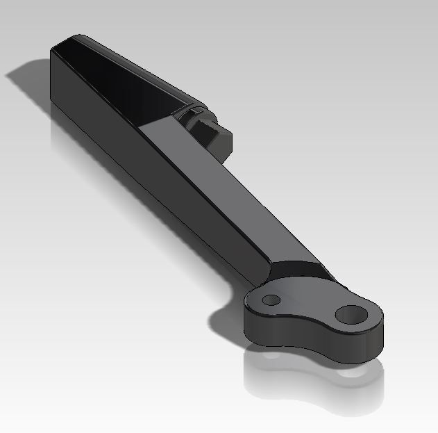
Here's my first little assembly, an adjustable tie bar.  Made it 'flexible' so I can specify how far the end piece is threaded (will do the same with the bottom arm etc) so in future I can change the caster/toe/camber when the full assembly is complete.


Tie%20Bar%20Assembly_zpsmaqsfnra.jpg


And I have made my new wheels as well, all rough dimensions from my head until I can take one into work in bits and gradually model it up :)


Capture_zpsd8eabbud.jpg


#2 MIGLIACARS

MIGLIACARS

    Up Into Fourth

  • Traders
  • PipPipPipPipPipPipPipPipPip
  • 2,057 posts

Posted 09 September 2016 - 06:43 PM

The adjuster part in the middle really needs to be a nut welded on, as on a car the chances are it will round in a short period of time,


I made my own a few years ago as on big power big brake big slick tyred cars they seem to break,


If you would like ill add some photos of mine,  I sold 2 sets but the costs of manufacturing them was  expensive compared to the kad ones that are available.


#3 Mini 360

Mini 360

    Up Into Fourth

  • Members
  • PipPipPipPipPipPipPipPipPip
  • 4,933 posts
  • Location: Aberdeenshire
  • Local Club: Independent

Posted 09 September 2016 - 06:55 PM

The adjuster part in the middle really needs to be a nut welded on, as on a car the chances are it will round in a short period of time,


How do you suggest I do the above to my tie bar which I measured in order to make the above model? :lol: that's a depiction of the bar I currently own, not one of my own design :)

#4 Readers14

Readers14

    Speeding Along Now

  • TMF+ Member
  • PipPipPipPipPip
  • 408 posts
  • Location: Guisborough

Posted 09 September 2016 - 07:00 PM

Good work.

What CAD system you using?

#5 MIGLIACARS

MIGLIACARS

    Up Into Fourth

  • Traders
  • PipPipPipPipPipPipPipPipPip
  • 2,057 posts

Posted 09 September 2016 - 07:00 PM

buy a nut counter bore it to the shaft size slide it down to about the center and tack weld it 2 on either side. :proud:


#6 Mini 360

Mini 360

    Up Into Fourth

  • Members
  • PipPipPipPipPipPipPipPipPip
  • 4,933 posts
  • Location: Aberdeenshire
  • Local Club: Independent

Posted 09 September 2016 - 07:05 PM

Good work.

What CAD system you using?

Thanks! Solidworks but it's an old version as my work predominantly use Pro/E Creo (which is ****) now and SW is used for legacy stuff.

#7 Mini 360

Mini 360

    Up Into Fourth

  • Members
  • PipPipPipPipPipPipPipPipPip
  • 4,933 posts
  • Location: Aberdeenshire
  • Local Club: Independent

Posted 09 September 2016 - 07:05 PM

buy a nut counter bore it to the shaft size slide it down to about the center and tack weld it 2 on either side. :proud:

that was more of a rhetorical question than a real one haha! :lol:

#8 Readers14

Readers14

    Speeding Along Now

  • TMF+ Member
  • PipPipPipPipPip
  • 408 posts
  • Location: Guisborough

Posted 09 September 2016 - 07:10 PM

Good work.
What CAD system you using?

Thanks! Solidworks but it's an old version as my work predominantly use Pro/E Creo (which is ****) now and SW is used for legacy stuff.

Yeah thought it was Solidworks.
We use Catia at work, mainly because that's what our customers use (Ford, Jaguar Land Rover, etc)

#9 Mini 360

Mini 360

    Up Into Fourth

  • Members
  • PipPipPipPipPipPipPipPipPip
  • 4,933 posts
  • Location: Aberdeenshire
  • Local Club: Independent

Posted 09 September 2016 - 07:13 PM

I se a lot of jobs advertised (not on my industry at the moment obviously as I'm sure you can imagine!) that ask for Catia. Once you learn one CAD, it's easy enough to pick up another. I use ProE, SW and then Inventor at college for example :lol:

My fiances brother works for Jaguar R&D and loves using Catia.

Edited by Mini 360, 09 September 2016 - 07:14 PM.


#10 MIGLIACARS

MIGLIACARS

    Up Into Fourth

  • Traders
  • PipPipPipPipPipPipPipPipPip
  • 2,057 posts

Posted 09 September 2016 - 07:16 PM

mine

Attached Files


Edited by MIGLIACARS, 09 September 2016 - 07:16 PM.


#11 smudger068

smudger068

    Speeding Along Now

  • Members
  • PipPipPipPipPip
  • 344 posts
  • Location: Ipswich

Posted 09 September 2016 - 07:20 PM

This is awesome stuff. And it's a shame that we didn't get more time in solidworks at uni to perfect something.

But my question is for a professional at this job how long does it take to create something like this? (More for appreciating what this is)
I'm guessing you could then apply the arm to a full subframe on another file say?

#12 Mini 360

Mini 360

    Up Into Fourth

  • Members
  • PipPipPipPipPipPipPipPipPip
  • 4,933 posts
  • Location: Aberdeenshire
  • Local Club: Independent

Posted 09 September 2016 - 07:33 PM

This is awesome stuff. And it's a shame that we didn't get more time in solidworks at uni to perfect something.

But my question is for a professional at this job how long does it take to create something like this? (More for appreciating what this is)
I'm guessing you could then apply the arm to a full subframe on another file say?

if I had Doms already, no more than an hour to make everything and mate it. Measuring everything, about 2-3. As with most things, it's the prep work that takes the time, the actual execution is fairly simple :)

#13 Itsjustanestate

Itsjustanestate

    On The Road

  • Noobies
  • PipPip
  • 43 posts
  • Location: Hull

Posted 10 September 2016 - 10:54 AM

This is something I have been thinking of doing for a while now. I already use CAD to make my model steam engines. It would be great to do an open source collaborative project for uprated parts.


About 200 hours CAD in the image attached.


Attached File  Loco.tiff   251.59K   52 downloads

Edited by Itsjustanestate, 10 September 2016 - 10:57 AM.


#14 Mini 360

Mini 360

    Up Into Fourth

  • Members
  • PipPipPipPipPipPipPipPipPip
  • 4,933 posts
  • Location: Aberdeenshire
  • Local Club: Independent

Posted 10 September 2016 - 09:33 PM


It would be great to do an open source collaborative project for uprated parts.


I broached the subject on here but the general consensus was that being able to rely on the modelling of various different people who don't know each other/their abilities, you could end up with dramatically inaccurate assemblies in no time.  The above will be used purely for my HND or personal project stuff I think :)


#15 Mini 360

Mini 360

    Up Into Fourth

  • Members
  • PipPipPipPipPipPipPipPipPip
  • 4,933 posts
  • Location: Aberdeenshire
  • Local Club: Independent

Posted 12 September 2016 - 01:56 PM

Todays lunchtime modelling was an adjustable bottom arm.  Only had 20mins to do it but got it 75% finished.  Little sub assembly wiht arm and the adjuster mechanism sleeve.


Bottom%20Arm_zps79rpuegt.jpg


Needs tidying up and the casting hollows removed at each side but the overall shape and hole location are fine.


Edited by Mini 360, 12 September 2016 - 01:58 PM.


0 user(s) are reading this topic

0 members, 0 guests, 0 anonymous users