I cut the micra drive shafts through the wheel arches, made it a lil easier


Grey 82 Mini Part 2, Micra Power.
Started by
tomgale
, Aug 11 2017 10:31 PM
30 replies to this topic
#17

tomgale
-
- TMF+ Member
-

- 561 posts
Super Mini Mad
Posted 24 June 2018 - 08:56 PM
This is very overdue an update so:

the micra got gutted,

the engine came out, and then the micra went to the scrapyard.
I toyed with making my own subframe, but I realised I just didn't have the time, so went down the allspeed route:

Now, this may well be my car, but while I could get the passengers side floor mounts lined up and bolted on without too much difficulty, the drivers side was quite far off, though I do remember that after I replaced the floorpans I did have to drill new mounting holes for the standard subframe, so they may have just been out. Either way I think I'll have to drill some new holes to get it properly secure.
Engine went in without too much grief:

started with the inlet manifold, original cut down and welded to a new plate:

then a 3D printed plenum chamber on top of that, with the throttle body bolted on. (in my excitement I may have forgotten to take any pictures of the inside of the inlet, with the trumpets etc. It'll have to come off again soon anyway, so I'll do it then.)

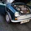
The engine bay as it stands now with the mini rad mounted:

Next on my list is the clutch, for which I plan on using the micra cable, and an unmodified mini pedal, with a bell crank lever to move from a push to a pull motion.
However, I seem to have misplaced my clutch bracket (the one near the lever that bolts to the engine/box) don't suppose any fellow micra-mini people have one they would sell me?
Thanks for reading!
#18
McMini 22
-
- Members
-
- 289 posts
Mini Mad
- Location: East lothian
Posted 25 June 2018 - 08:27 PM
Looking good.
More info on your plenum please!
Will 3d print be strong enough or are you fibreglassing it?
Also your inlet runners look pretty short which will be great for flat out but not much torque.
More info on your plenum please!
Will 3d print be strong enough or are you fibreglassing it?
Also your inlet runners look pretty short which will be great for flat out but not much torque.
#19
tomgale
-
- TMF+ Member
-
- 561 posts
Super Mini Mad
Posted 25 June 2018 - 09:15 PM
so it's made from carbon fibre filled nylon, which is pretty strong stuff, especially with the thickness that it is. The runners are super short, not out of choice but because of the limited space (although I have had to space the TB up by 18mm or so to clear the injectors, making it a bit longer), I'll have to see how it goes, I can always print a different design and try it later, beauty of printing!
#20
Andi-p
-
- Members
-
- 188 posts
Mini Mad
- Location: Darlington
Posted 25 June 2018 - 09:27 PM
Out of interest what size is the box section that is used to make the alterations to the front subframe?
#21
McMini 22
-
- Members
-
- 289 posts
Mini Mad
- Location: East lothian
Posted 25 June 2018 - 10:18 PM
so it's made from carbon fibre filled nylon, which is pretty strong stuff, especially with the thickness that it is. The runners are super short, not out of choice but because of the limited space (although I have had to space the TB up by 18mm or so to clear the injectors, making it a bit longer), I'll have to see how it goes, I can always print a different design and try it later, beauty of printing!
I see. You must have a nice 3d printer. I've just refurbished a Prusa printer at work. It can now print 4 different colours or materials as it has 4 filament drives through one extruder.
I was thinking of using it for my next plenum. I am intending to use the printer to make a mock up and then take a mold in fibreglass. Then carbon fibre, using a bladder inside to get a nice finish. Like vacuum bagging in reverse!
There's plenty room in there for a log type plenum. That should give more scope for design. I'm now using Solidworks CAD package which has a flow simulation package in it. Could get interesting!
#22
tomgale
-
- TMF+ Member
-
- 561 posts
Super Mini Mad
Posted 26 June 2018 - 08:48 PM
we have a couple at work, they are far nicer than anything I could afford! I did consider a log style, but I wanted to maintain the original orientation of the throttle body, which limits height a lot, the plan is to have a carb looking air filter on top, trying to keep it as standard as possible! I use solidworks too, big perk of work is access to all the kit! Printing moulds should work really well.
as for the box section, I've no idea as the frame was bought from allspeed
#23
lawrence
-

- Members
-
- 1,341 posts
One Carb Or Two?
Posted 27 June 2018 - 08:34 PM
That plenum is amazing. I hadn't even thought how 3D printing can make things like engine conversions etc so much easier.
Could you 3D design an entire rocker cover? And then print it out in an older style like the Ali metro one for example. Would totally confuse people and look great!
Keep it up!
Could you 3D design an entire rocker cover? And then print it out in an older style like the Ali metro one for example. Would totally confuse people and look great!
Keep it up!
#24
tomgale
-
- TMF+ Member
-
- 561 posts
Super Mini Mad
Posted 28 June 2018 - 07:02 PM
you could do a rocker cover, but the nylon material starts to soften at around 140 degrees, which might be a struggle with oil, plus for that printer it'd be way too big, what you might be able to do is a lost plastic casting in alu with a printed former, which would look pretty awesome!
#25
tomgale
-
- TMF+ Member
-
- 561 posts
Super Mini Mad
Posted 17 June 2025 - 01:19 AM
So I think its about time I finish this thread, Spoiler alert, the mini got finished, but it met an untimely end. I've mean meaning to update this for years, but never quite managed to get around to it, there's a lot of stuff to cover, and hopefully it's of use to people. So, lets jump in the time machine back to the distant year of 2018.....
First off, a few more pictures of the inlet manifold, you can see here the laser cut spacers to lift the throttle body up:

And here you can see where I didn't get away with printing without supports and had to use a bit of epoxy to sort out the failed bits:

This plate goes against the aluminium face of the intake manifold and has the intake trumpets on it, the strange shape is based on the cross section of the inlet manifold where I cut it:

I was pretty new to printing back a this point, and there were a few iterations after this, the main problem with this first one was it flexing under the vacuum at closed throttle, so I ended up thickening it up and adding a few more ribs, but the trumpet plate stayed the same.
The clutch setup I mentioned earlier ended up looking a bit like this (parts on the bench to show how it works):

And installed:


clutch cable end:

This worked pretty well, The base plate, lever and posts are aluminium, and the mounts for the pivot and clutch cable are printed in nylon. I ended up moving the pedal-side mounting hole a little closer to the pivot to get the ratios right, and the rubber wore out constantly (I used the boot from a late mini brake servo master cylinder). I also seem to remember there are two lengths of clutch cable available, and I think you need to use the longer one for this set up.
For the alternator, I managed to get hold of a little denso alternator from a friend who was converting a suzuki cappucino to electric a the same time. I mounted it by re-making the cam timing plate in thicker aluminium, and adding a lug at the rear, and some holes for a vertical post. The fixed end is on the lug, with a turned spacer to put the alternator at the right distance, with a countersunk bolt into the threaded hole on the alternator. A turn buckle between the other mounting hole and the vertical post provide adjustment. The belt has to take a bit of an odd route, I removed the power steering pump of course, so there is a micra belt from an early car with no PS linking the water pump and crank pulley. Then another pulley is fitted on top of the water pump pulley (this needed a special part turning to centre the second pulley and stop it vibrating), to link the water pump and alternator with a smaller belt:


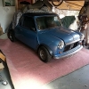
A few misc bits, found an electric fan that fitted nicely in the shroud, then put the shroud on backwards so that the fan was on the wheel side. I mounted the radiator with a big plate on the front picking up on two of the shroud mount holes, and a little one at the back attached to the crossmember picking up on the top hole on that side. Then I found a few bits of rust, and since I wasn't set up for welding at this time I ended up trailering the car to a local specialist to get the patches done, while balancing it on a slightly dodgy pallet:


While the shell was away being sorted I got the subframe built up. I decided to go BMC engine green, and did the rocker cover in crackle black after grinding off the nissan logo. I rattle canned the gearbox silver as it didn't clean up that nice. Suspension was mini spares rose jointed adjustable bottom arm, with the heavy duty tie rods modified by cutting the end off and turning a left hand thread on for a rose joint so the length could be set on the car. Note that the passenger side injector is turned 90° to let the connector clear the throttle body (I just filed a second slot in the retaining plate).


Once the car was back I got the subframe back in, and started hooking things up For the air filter I printed a blanking plate for the top and an adaptor ring for the bottom and just re-used the original filter and housing For the exhaust I just cut the manifold and welded a tube on, with a bolt on 90 to connect back to the original manifold. I was planning on changing to a nicer fully welded one at some point, but never got round to it:


For the gear lever I cut and shortened the micra one, added a bit of threaded bar to the selector rod so I could find tune the position (though I don't think I ever changed it). Then made an aluminium piece to adapt it to the mini mounting holes:


Then, with a new sticker number plate I went to Green and White in durham for an MOT and suspension setup. A few teething issues and then I was able to use the car daily, and for a few track days:


The interior was always a bit of a work in progress while I used the car, I made a crackle black switch panel with toggle switches and lights, and started mocking up a panel below the passenger dash rail for the micra fuse box. The heater got a new fascia with levers for the diverter valve which was mounted just above the fuse box. I designed a pcb for a Bluetooth radio to fit where the original fog light switch panel went, with knobs where the choke and heater cables originally were. I only really have reference images I took for these, so they're a bit rubbish.


A quick dump of learnings on immobilisers etc (though take it with a pinch of salt, I havent thought about this in about 4-5 years, I suspect for a time I may have been the leading expert on micra ECUs...) . The donor was a facelift micra with NATS 2 (red chip) I wanted to keep the immobiliser, so I took out the chip, cut a hole in the mini's rubber key, shoved the chip in, and heat shrunk it. Then I mounted the antenna inside of the steering column shroud, cutting the bottom for clearance. This worked really well, but the key only worked in one direction. I got used to feeling the chip with my forefinger, so I could start it every time, but others had a 50/50 chance, I figured this was just more security, so never fixed it. During troubleshooting some issue I cant remember, I though the ECU might be the problem, and wanted to try a non-NATS one, these have a different pinout, so you cant just swap them. BUT, you just need to swap a couple of pins to make it work. since the sockets are the same. I cant remember which ones, I have a diagram somewhere, and I wont post it anyway since it might help thieves. But if you need the info DM me and I'll try to dig it out.
#26
tomgale
-
- TMF+ Member
-
- 561 posts
Super Mini Mad
Posted 17 June 2025 - 01:22 AM
(Split post for image limits)
So, now to discuss the reason this post is noticeably in past tense. As I mentioned at the start the mini sadly met its end in 2022.
GRAPHIC CONTENT WARNING: INJURY AND CRASH IMAGES AHEAD.
It might be a bit strong for some, if you're squeamish, I'd perhaps stop reading now. I wont post the worst of the bloody ones, but I'll share some X-rays/CAT scans and images of cleaned wounds. Fell free to stop reading, but I feel like it's important to confront the reality of what having an accident in a design from the 50s looks like. It wont stop me from driving a mini, and I don't think it should stop you, but if it makes you take a bit more care, then it's worth it.
5th of August 2022:
It had been a strange day, My friend's electric cappuccino project ( next to the mini in one of the earlier pictures) had spectacularly burnt to the ground round the back of work, leading to all of us stood in the car park watching two fire engines empty their tanks onto a lithium battery fire. I stayed back to help another friend with his lifted subaru legacy project. We were late leaving as the alarm was playing up, I was getting impatient as I needed to get home to let my wife get some sleep, as our son was 3 months old at the time. I was driving back, reflecting on the day and thinking how gutted I'd be if I lost my car in the same way. I remember being in a queue of cars on a 40 mph stretch of road near home, then nothing, then waking up with a feeling of dread, broken glass everywhere and shouting outside the drivers window.
A ******* in a modern Golf, off his face on cocaine had come round the corner way too fast, lost control, scraped along the side of the car in front and smashed into the front of the mini. I have no memory of the collision itself. No idea if had time to brake, or take evasive action. The images show the mini quite far into a hedge, perhaps I dodged, perhaps I was shoved by the force of the crash. The police estimated the combined speed to be 70mph.

the bulkhead was pushed back maybe about 200mm, completely buckling the A-pillar and pinning me into the seat. Pumped full of adrenaline I tried to push the bulkhead off myself to climb out, much to the alarm of the people outside of the car. I didn't realise it, but my right leg had been shattered, my lower leg was snapped and wrapped round the pedals, and my femur had been blown apart from the impact, a fragment of bone had exited my leg and speared straight through the screen of my phone. My little finger on the right side was broken, and my forearm was shredded from the door glass. When I checked the car over later I found chunks of my hair stuck in the cracked paint on the outside of the drivers door, the force of the crash might have folded me completely outside of the window. I pleaded with the fire fighters not to cut the roof off, which of course they sensibly ignored. The last thing I recall is the air ambulance doctor injecting a cocktail of ketamine, morphine and fentanyl into me through the windscreen to sedate me for removal. I was stuck in the car for around two hours. The fire fighters later told me they had me nearly fully out before realising I was wrapped round the pedals, and had to put be back before they could untangle me. I came to in a CT scanner in hospital, then went for surgery in the morning to have two titanium rods inserted the full length of my leg bones. The surgery took 8 hours to complete due to the state of my femur.
A CT scan post accident but pre surgery showing damage to the leg:

X rays of the repaired leg:


Damage to my forearm:

I spent two weeks in the trauma ward. Huge kudos to anyone in the medical profession, I have no idea how they do what they do. If you remember this was during a huge heatwave, and I remember waking up on the plastic mattress in the sweltering ward in a pool of sweat. I couldn't sit up without passing out as I'd lost so much blood, it really was the most horrific experience.
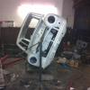
Once I was finally out I went to see the remains of the mini in the police yard. The damage was striking, particularly how small the door opening now was, the gear lever was completely inside the heater, showing how far back the bulkhead had come. My bucket seat was completely deformed having possibly saved me from far worse injury:


I eventually got the mini brought home, so I could salvage what I could:


I managed to pull the complete rear subframe, rear lights, petrol tank, engine, front suspension and subframe and suspension, most of the dash, exhaust and the wheels. The subframe held up well, bending as you'd expect but no welds failed, so thanks Allspeed, you might have saved me... The drivers side tie rod snapped, and the wheel is buckled, but the rest of the suspension seems fine, the impact snapped the water pump off the engine block, but otherwise it seems ok. All the bits live in my garage now, waiting for another project.
As for me, I suppose I got quite lucky. No airbags, no headrests and somehow, no head or neck injury. It took more than 2 years and another round of surgery before I could use my leg properly, and its still not back to where it was.
So that's my story, not a happy one, but worth telling I think. When the insurance payout gets sorted, I'll definitely have another mini, doesn't feel right not having one.
(edit, managed to duplicate the post, that'll teach me to post while tired!)
Edited by tomgale, 17 June 2025 - 06:25 AM.
#27
68Deluxe
-

- Noobies
-
- 49 posts
On The Road
- Location: Avoca Victoria
Posted 17 June 2025 - 05:35 AM
Hollly Molllllly!
You are lucky to be here telling the story!
#28
Steam
-

- Members
-
- 935 posts
One Carb Or Two?
- Location: Vic
- Local Club: Victorian Mini Club
Posted 17 June 2025 - 07:23 AM
While its best to say the car is only metal and your life is more important, what a shame. Hope you are now doing ok health and mentally wise. You and your Mini deserved better after all the hard work you putinto it.
#29
Rubbershorts
-

- TMF+ Member
-
- 700 posts
One Carb Or Two?
- Location: Bradford-ish
Posted 17 June 2025 - 11:17 AM
Christ, that's shocking. Glad you're here to tell the tale. What happens next? Can it be re-shelled and keep it's original reg? Daz.
#30
stuart bowes
-

- TMF+ Member
-
- 2,577 posts
Up Into Fourth
- Location: Dagenham
Posted 17 June 2025 - 12:57 PM
phew glad you're alright, that's a proper mess they cut you out of there
'please don't cut the roof off' amused me though haha
any news on what happened to the nob head in the golf, hope they got a decent punishment
Edited by stuart bowes, 17 June 2025 - 12:57 PM.


0 user(s) are reading this topic
0 members, 0 guests, 0 anonymous users


