A little bit of bling!
I have replaced the old HT Leads.
 IMG_2412.jpeg 92.24K
0 downloads
IMG_2412.jpeg 92.24K
0 downloads
with these shiny new ones
IMG_2414.jpeg 97.32K
0 downloads
Edited by DUF2, 15 August 2023 - 10:11 AM.
Formally known as DUFfi

Posted 06 August 2023 - 12:21 PM
A little bit of bling!
I have replaced the old HT Leads.
IMG_2412.jpeg 92.24K
0 downloads
with these shiny new ones
IMG_2414.jpeg 97.32K
0 downloads
Edited by DUF2, 15 August 2023 - 10:11 AM.
Moderator

Posted 06 August 2023 - 07:38 PM
Just read through the whole project, great read ! can't believe how much filler you found!
Pretty sure RED ht leads give you an extra 50bhp 
Formally known as DUFfi
Posted 15 August 2023 - 10:16 AM
I have discovered the problem with the handbrake.
The cable return springs are becoming coil bound so are preventing the cables pulling sufficiently on the actuating lever.
I was going to shorten the spring but I am still not convinced these cables are correct so have ordered a new set, don’t know why the photo is upside down!
IMG_2457.jpeg 80.92K
2 downloads
Formally known as DUFfi
Posted 19 August 2023 - 11:16 AM
The cables on the car were the correct ones! The new ones are the same length, albeit the spring is finer so it should not get coil bound.
However it now looks like the operating lever is the problem. The lever comes out of the brake drum at 90 degrees so the movement to operate the handbrake is compromised. The notches in the lever, whilst not appearing to be worn, must be too deep.
I have filled the notches on one operating lever with weld and the handbrake works, just got to do the NS now
Formally known as DUFfi
Posted 19 August 2023 - 05:24 PM
Here are a couple of pics of the operating levers before modification
IMG_2496.jpeg 74.88K
0 downloads
and after, you can see the notches are quite deep in the before shot.
IMG_2500.jpeg 93.19K
0 downloads
The notches are a lot shallower after modification. You will notice I had already extended the length, to give a little more leverage. The handbrake feels a lot better now.
One Carb Or Two?

Posted 19 August 2023 - 07:13 PM
Are you sure that that the drums are not too worn? It might be worth measuring the diameter to check.
It may also be an issue with the shoes as i've found some of the newer ones (last 10 years or so) are not made correctly creating this issue.
I've seen people weld up the arms before but only when the shoes or drums were at fault as a fix to keep the car on the road.
Crazy About Mini's

Posted 20 August 2023 - 07:54 AM
Formally known as DUFfi
Posted 20 August 2023 - 06:15 PM
Are you sure that that the drums are not too worn? It might be worth measuring the diameter to check.
It may also be an issue with the shoes as i've found some of the newer ones (last 10 years or so) are not made correctly creating this issue.
I've seen people weld up the arms before but only when the shoes or drums were at fault as a fix to keep the car on the road.
The drums are brand new.
Formally known as DUFfi
Posted 20 August 2023 - 06:16 PM
Although your extension gives more leverage it also increases the throw, which will be why your cables were getting coil bound.
Graeme, no problems with coil binding now I have adjusted the operating levers, the handbrake works fine.
Formally known as DUFfi
Posted 20 August 2023 - 06:25 PM
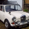
The insurance is due soon for Duffy. I enquired about agreed value and was told I just needed photos. So here are the ones I took.
IMG_2501.jpeg 115.38K
0 downloads
IMG_2502.jpeg 113.47K
0 downloads
IMG_2503.jpeg 120.29K
0 downloads
IMG_2505.jpeg 124.97K
0 downloads
IMG_2507.jpeg 85.2K
0 downloads
IMG_2508.jpeg 91.11K
0 downloads
IMG_2512.jpeg 71.53K
0 downloads
IMG_2513.jpeg 98.39K
0 downloads
it is not looking too shabby, despite needing a good clean & polish
Formally known as DUFfi
Posted 26 August 2023 - 10:49 AM
I have been struggling with the Sun Visor mountings. The plastic clips I bought to hold the end of the visors near the mirror, were fitted OK but have since broken. I reordered some from a different supplier and these have now been swapped out.
IMG_2539.jpeg 52.1K
0 downloads
On the same order I bought a couple of the visor side mount clips, however I could not find the holes in the head rail.
IMG_2537.jpeg 38.63K
0 downloads
I asked on this forum if anyone had any measurements where the hole is, but got no response. I trawled back through all my photos and found this old photo, no it is not in black & white!
IMG_1635.jpeg 33.11K
1 downloads
Armed with the Photo, I was able to feel in the correct location, I found the hole and both clips are now fitted.
IMG_2543.jpeg 52.16K
0 downloads
So that is another job ticked off the list, still a load more to do!
Formally known as DUFfi
Posted 09 September 2023 - 02:55 PM
Those of you following my build will know I have been having trouble with the speedo, see post #129.
I had bought a replacement speedo which should have the correct gearing, so I set about swapping this over. First issue I have is the instrument lighting, the speedo illumination is rather dull, whilst the Tacho I fitted has a nice bright illumination, presumably LED. I had changed the bulbs in the speedo for LEDs but the speedo was still not much brighter.
IMG_2571.jpeg 17.51K
0 downloads
the new LED instrument illumination bulb.
The inside of the speedo housing is a light blue colour, not the best for reflecting light. I had the bright! idea of lining the speedo housing with mirror silver vinyl wrap to reflect the light from the bulb.
IMG_2564.jpeg 80.68K
0 downloads
this is the “new” housing.
When I removed the original speedo I discovered the mounting brackets were different on the Elf, so I had to use the existing housing, so this was lined with the vinyl wrap.
I was also concerned that the replacement speedo had had the odometer reset to zero. I wanted the mileage of 90187 as shown on the original odometer in the replacement speedo. I did not want to attempt to dismantle the odometer, I did one years ago and struggled to get all the springs, washers, counter wheels re assembled.
When I examined the 2 odometers side by side, I could see they were not the same, the original one has the ratchet wheel inboard the mounting bracket, the newer one has the ratchet wheel outboard of the bracket,
IMG_2568.jpeg 17.86K
0 downloads
This pic shows the top half of the mechanism, with the yellow ratchet wheel outboard of the bracket.
also the counters and the mounting could not be removed without dismantling the drag cup from the shaft which the speedo needle sits on, bugger.
I searched the internet but could not find any info on how to release the mechanism to reset the counters. The next thing was to wind the odometer from zero to 90K! With the ratchet pawl removed I was able to rotate the ratchet wheel be hand, but it would take an age! So I tried my electric drill on the end of the shaft, the mileage started to increase, I was concerned the drill may overheat things so kept doing it in batches of 5K. I did discover the when more than 2 digits were changing it got harder to turn. I got the mileage upto 19K then things got tight again and something stripped on the 10ths digit. The Odometer was now kfuced!
Time for a rethink, I examined the 2 speedos and realised the mechanism was split in two, the top half contained the drag cup, needle spindle and the odometer, the bottom half contained the speedo input shaft, the worm drive and the magnetic wheel.
IMG_2567.jpeg 41.44K
0 downloads
This is the original lower half of the mechanism.
So I elected to put the original top half & odometer onto the “new” bottom half.
I assembled all the parts, fitted the speedo into the wooden centre dash and started to wire everything back up. Before bolting it all back together I checked all was operating as it should, I have a voltmeter hiding in the glove box, the voltage showing started fluctuating. I checked the wiring and discovered I’d left a wire off the voltage stabiliser. I refttted the wire then checked all was working, the fuel gauge went up to half full, then started to drop to zero. It looks like the voltage stabiliser is goosed, I have ordered a new solid state one.
I did take the car out for a short run to check the speedo operation, the needle no longer fluctuates but it still under reads, it looks like someone has changed the speedo drive gear in the gear box. At 30 mph on the gps on my phone, the car reads 25mph, I tried to run the car upto 50 on the A1, but traffic was only doing 25 mph! I shall have to try again when the traffic is easier.
As I said I’m fairly sure the voltage stabiliser is passed it’s best, so I have bought one of these solid state devices which I need to wire in. It is a shame the wires for it are so short!
IMG_2570.jpeg 25.12K
0 downloads
new voltage stabiliser.
I will have to extend these to allow connecting up the unit.
Moderator
Posted 10 September 2023 - 06:02 PM
That's a nifty little SS voltage stabiliser you have there, I have seen a similar one on a Landrover website that looks like a little PCB, but when i searched i had gone by part number and couldn't find an exact match,.. It's something i wanted to fit to my City E that has the poverty-spec Center binnacle, which i love! Why on earth didn't i think to just do a basic google search for 10v voltage stabiliser, I do not know. Mind you,... I have enough on the go right now.
Looking forward to seeing the new speedo illumination in action! I'm sure it'll make a difference - I have noticed a trend <on various other restoration forums> for going with gloss white on the inside of these housings, I'm sure a mirror finish such as yours will also work pretty well!
Formally known as DUFfi
Posted 11 September 2023 - 03:36 PM
The voltage stabiliser works! It is just a shame there is only a single spade on the input. On my original stabiliser there were 4 wires. 2 on piggy back spades which plugged onto the dual male spade on the regulator.
I had to make up a small link cable with 1 female spade on one end, then a male spade on the other end with another cable coming out of that to a second male spade.
Plugged it in and all works fine, but the fuel gauge does not go quite as high as it did on the original stabiliser, however the new one may be the correct reading! I suppose I’ll have to brim the tank to see what the gauge reads then. To be honest the E reading will be the most important one!!!
Formally known as DUFfi
Posted 27 January 2026 - 05:01 PM
Sorry, I have been a bit lazy and not updated this for a while.
i recently took Duffy out on a Classic tour, the longest distance the car has done in my hands. The Oil got hot and the pressure dropped towards the end of the run. The car has a sump shield fitted which is preventing the air flow cooling the sump.
i have bought a 10 row cooler kit but am struggling to get this fitted to the car.
I can’t fit it horizontally as it contacts the Starter, distributor or alternator.
i have tried to fit it vertically, I thought I was nearly there but then discovered I couldn’t get the hoses to fit, they seem a bit short.
Any ideas or tricks to fit this to the Elf?


0 members, 1 guests, 0 anonymous users


