1979 Mini Marcos
Started by
maph2
, May 05 2020 09:06 AM
44 replies to this topic
#16
Posted 05 May 2020 - 09:26 AM
Klingon bonnet bodge job by the PO. All scrap.
#17
Posted 05 May 2020 - 09:28 AM
Last night's first job was to start beefing up the steering rack mounts. They mirror the design as per mini but can collapse as the GRP can weaken. I made up some GRP flat sections which sat on 5mm of grp filler which was slapped over the holes. Once hard I'll lay over some CSM before redrilling the clamp holes
Next up was laying in 4 layers of CSM and one layer of roving to repair the outer surface of the drivers side heel board mount. You'll recall I had previously glassed from the inside with CSM, roving and carbon. Glass was extended round to the outer wheel arch to tidy the joint up and to strengthen that wheel arch corner panel.
#18
Posted 05 May 2020 - 09:33 AM
Carbon fibre bracing going in.
Choppy chop, slicey slice.
More powdercoating collected this morning. Got the tank done in silver, everything else in RAL 6011. Rear beam is back so can finish of the heel board mounting points. I need to check they are correctly positioned.
This afternoon I've filled in the gap and glassed in from the rear to lock in the new lower back panel section. Also started to trim the bumper corner sections. Letting in some thin GRP sheet, glued in with GRP filler then glassing in from the back with CSM and a layer of tissue at the front. Getting this panel finished will take a while, especially as it'll need a lot of fine surface filling and blocking back to get the panel level.
Roll hoop picked up this week along with some other tubing, to build the rear frame to support the rear beam and coilovers. 50mm OD CDS tubing probably overkill.
Today I hacked the front about, out of boredom and curiosity to see exactly how curse word the workmanship is.
Drivers side rear most rear subframe mount repaired. As I'm running a "beam axle" set up, these rear most mounts won't be used, so it's a patch up.
#19
Posted 05 May 2020 - 09:44 AM
This is the passenger side rear mount. Totally exploded as the steel as rotted. Chiseled the rust out then made a cardboard template for patches. I'm using sheet PCB circuit board which is cheap from eBay. 1.5mm thick, 2 layers with CSB and resin sandwiched in between. Wedged in place
Once cured, a skim of filler to smooth. No load here so it's just cosmetic.
Both heel board ends have been repaired so have offered up the beam. Just an approximate location for now to get 2 small bolts in place to hold it up. Then I'll take a number of measurements to get the beam as square as possible to the shell before drilling all 8 mounting holes. Ride height, camber will be adjustable and the beam will be shimmed at final set-up anyway.
#20
Posted 05 May 2020 - 09:53 AM
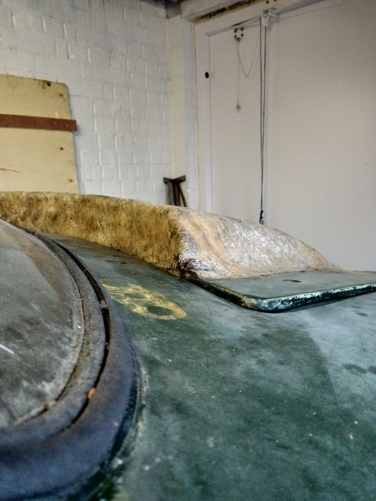
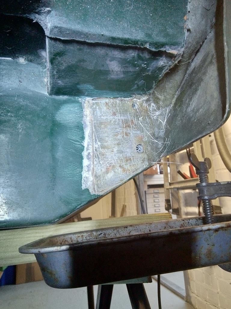
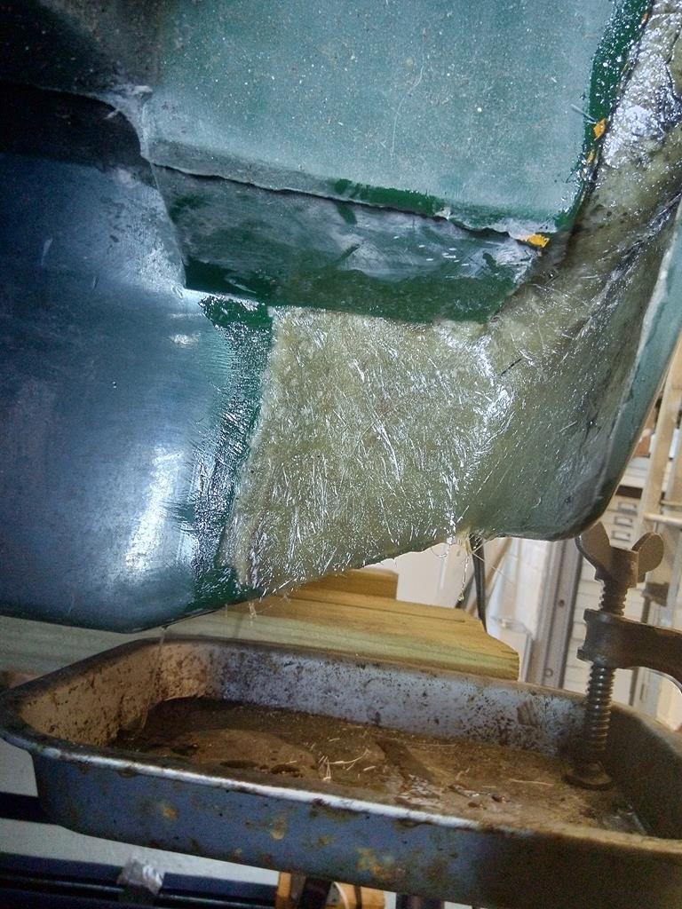
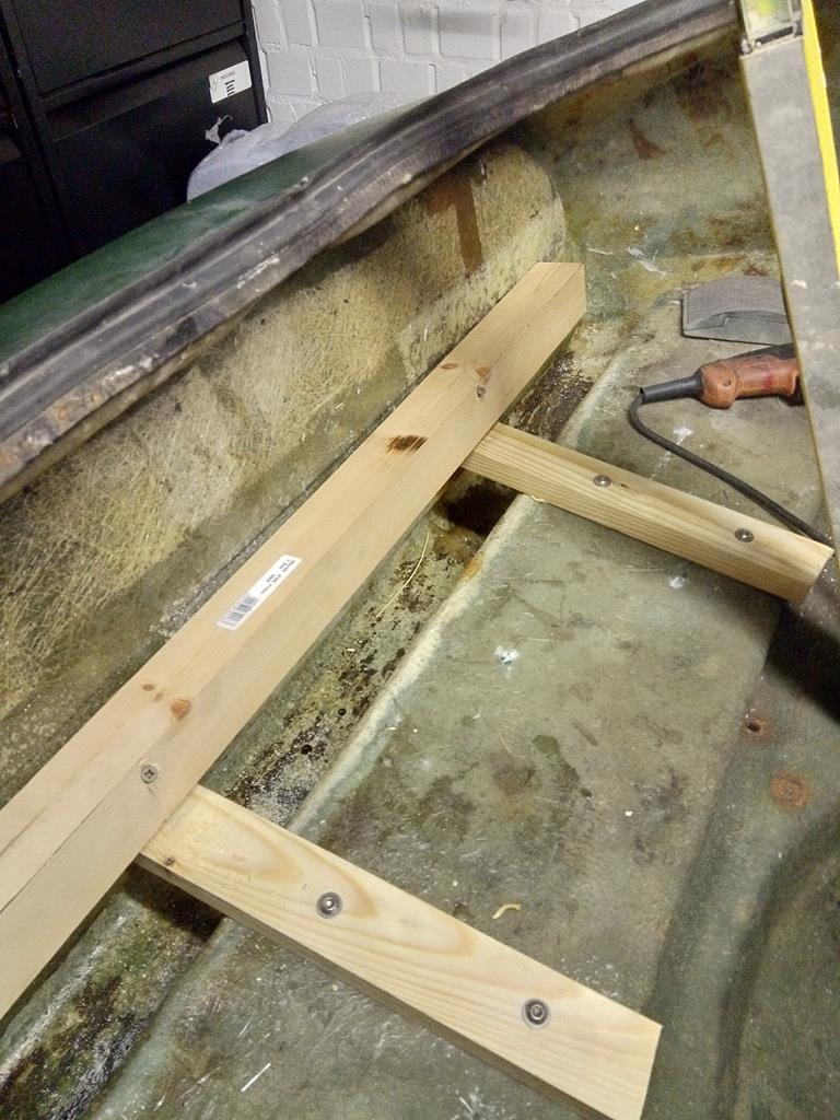
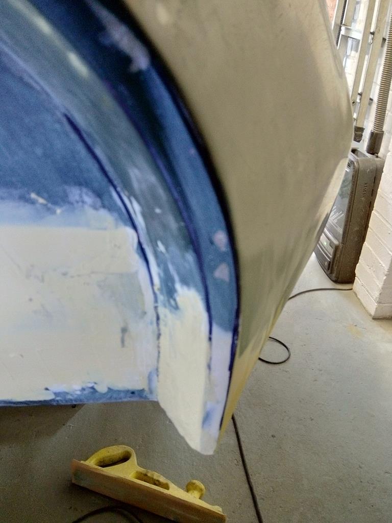
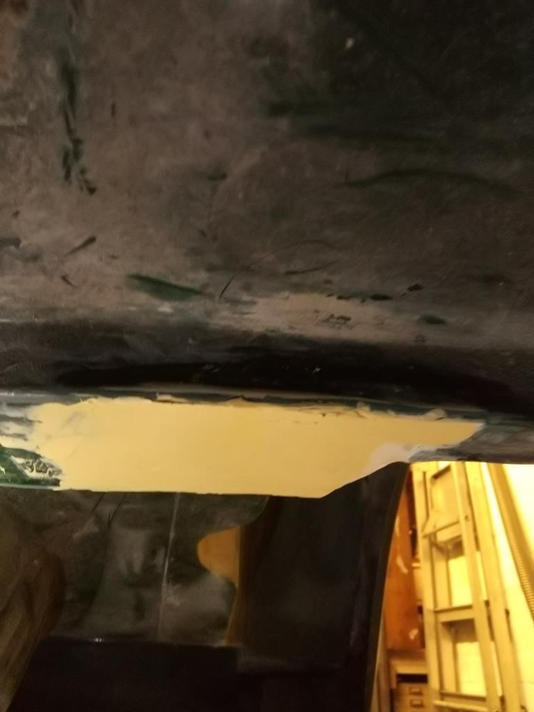
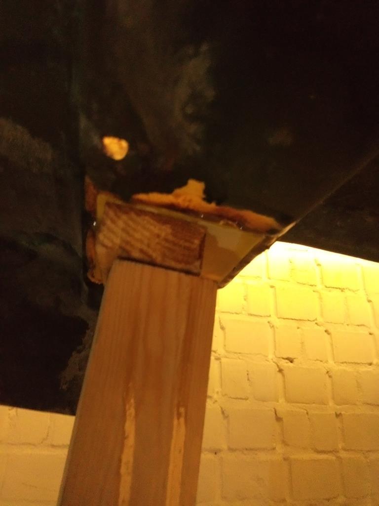
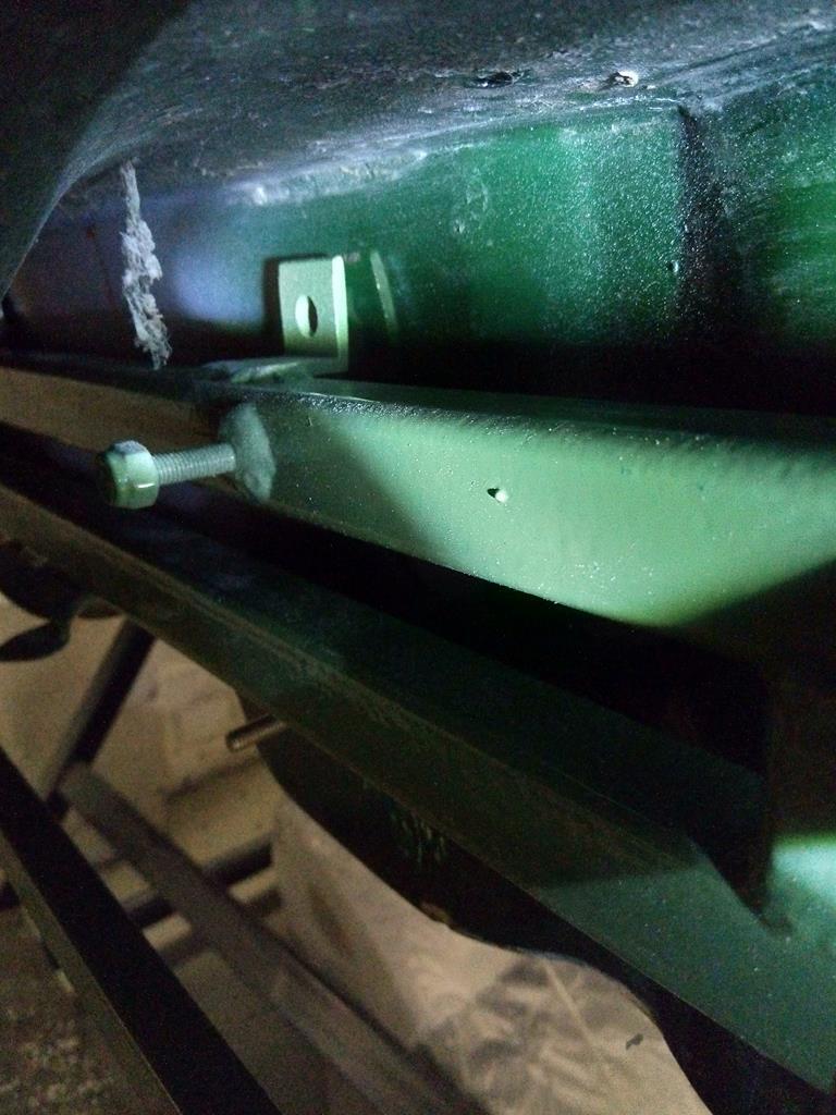
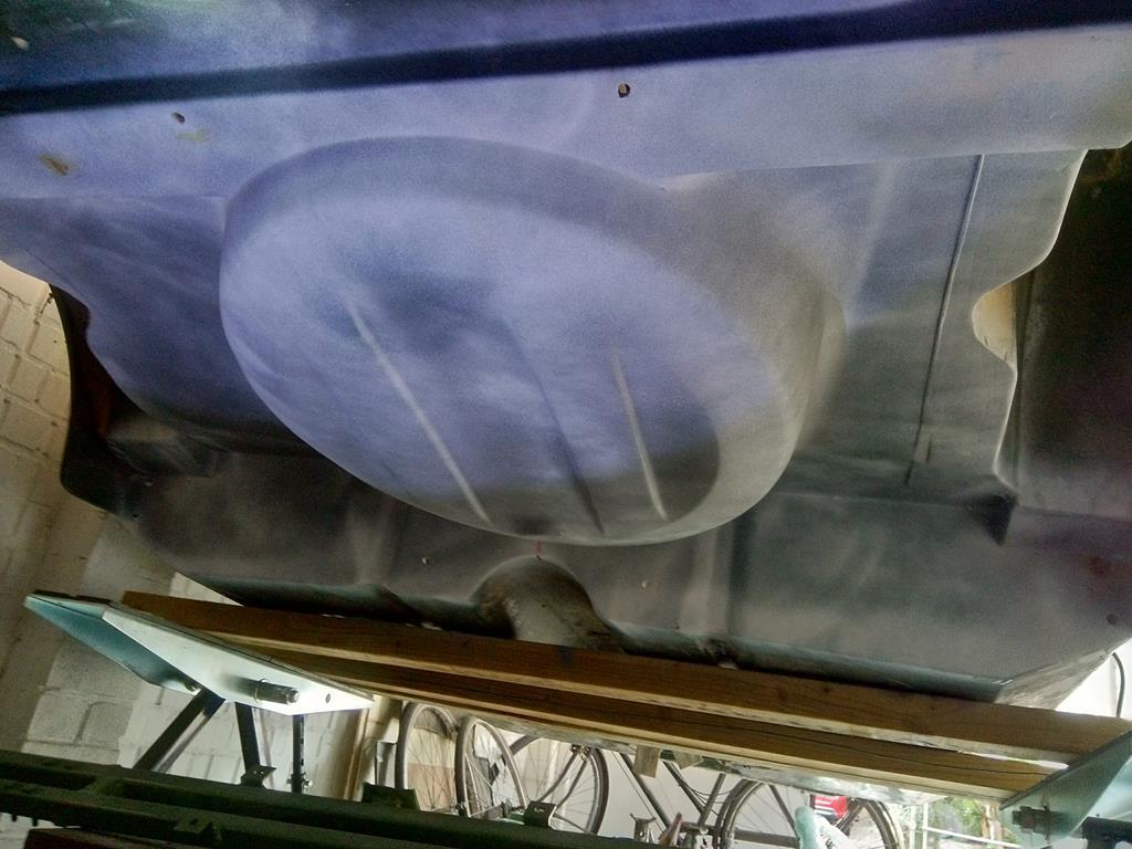
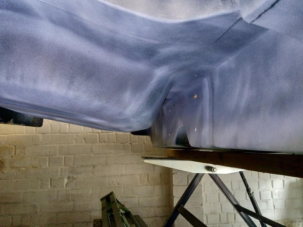
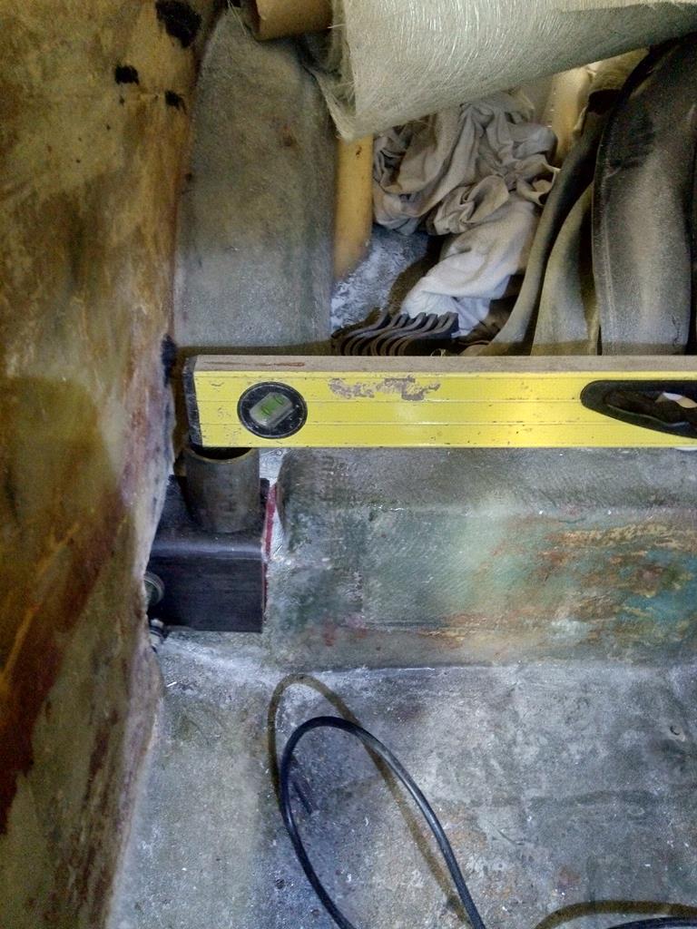
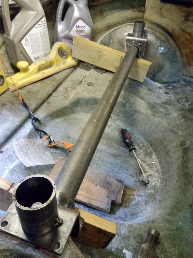
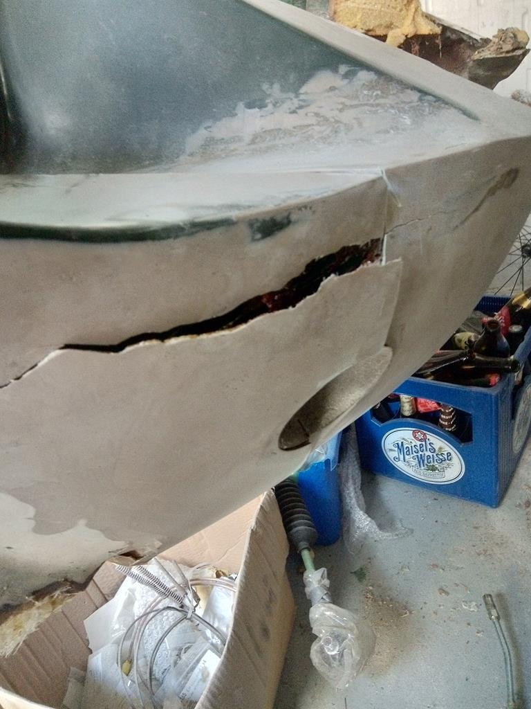
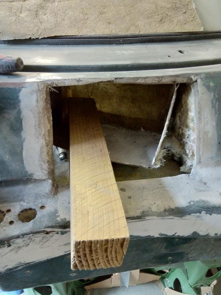
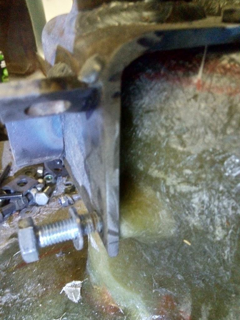
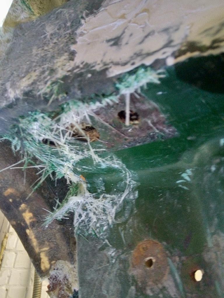
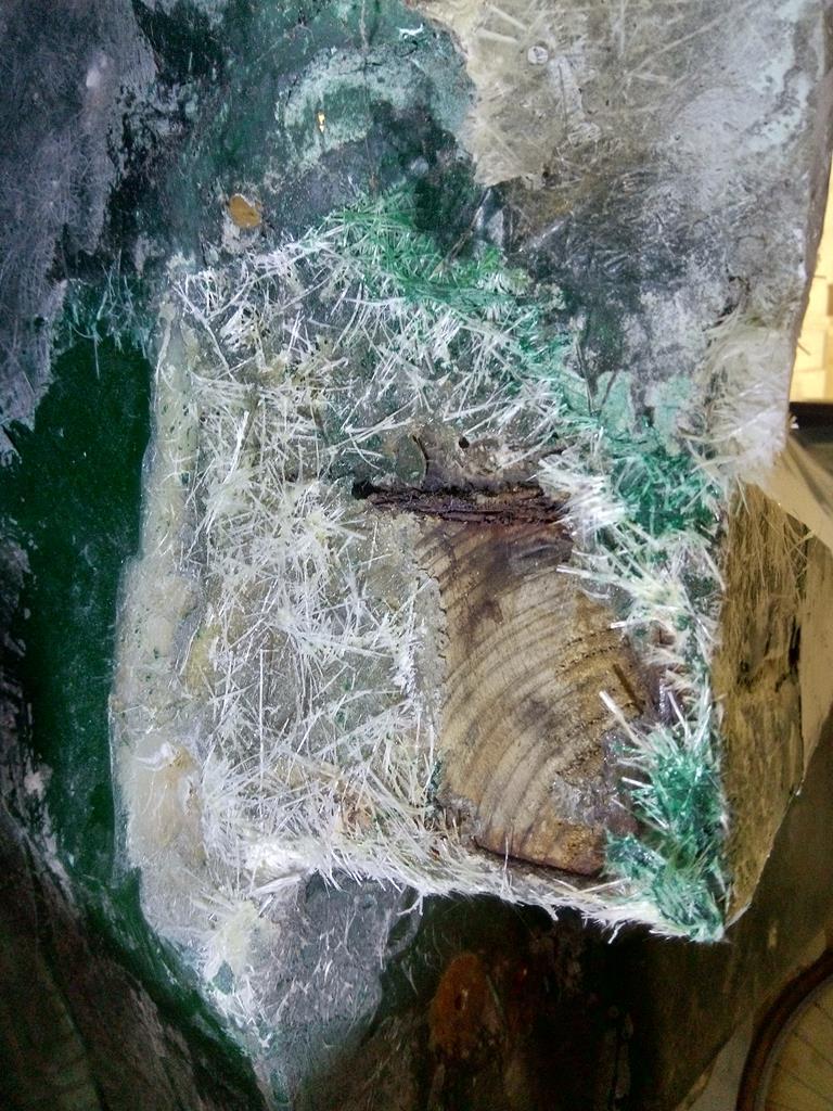
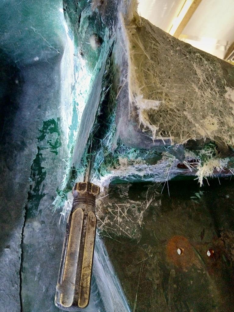
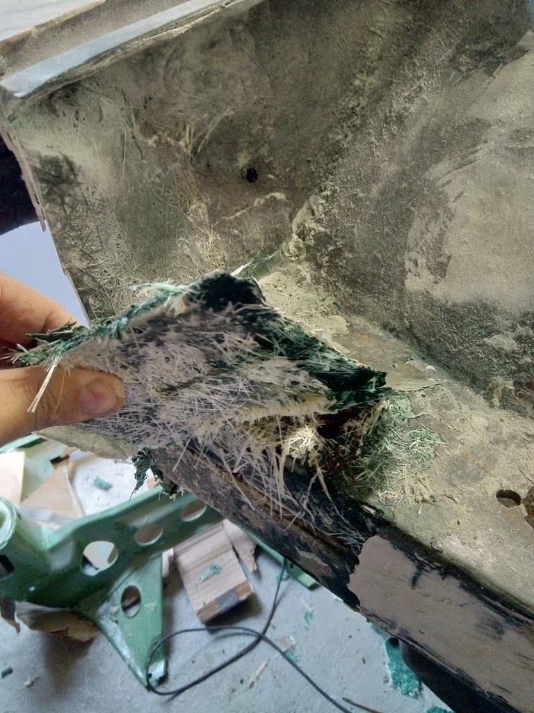
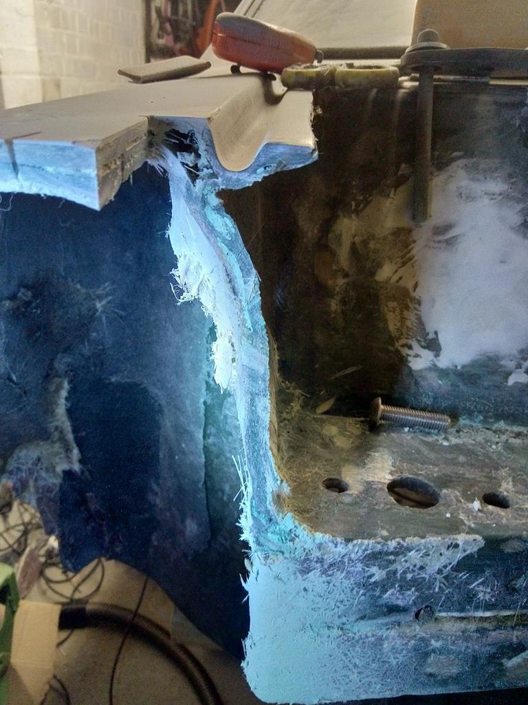
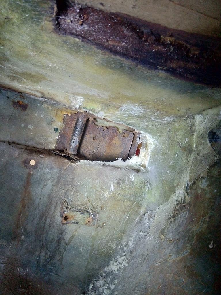
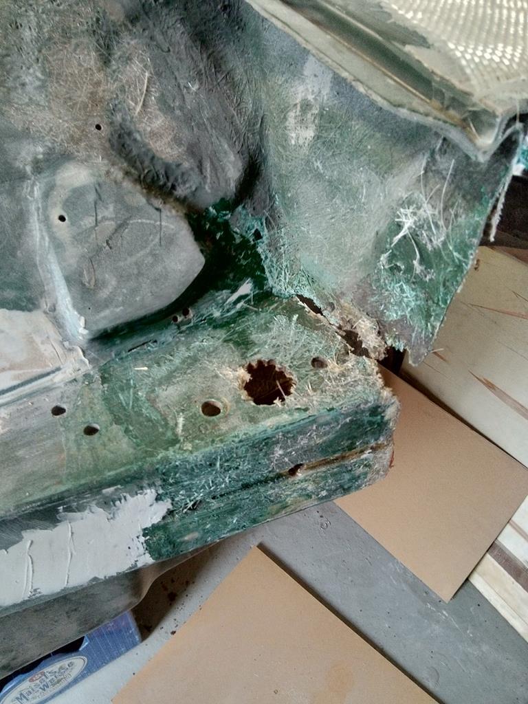
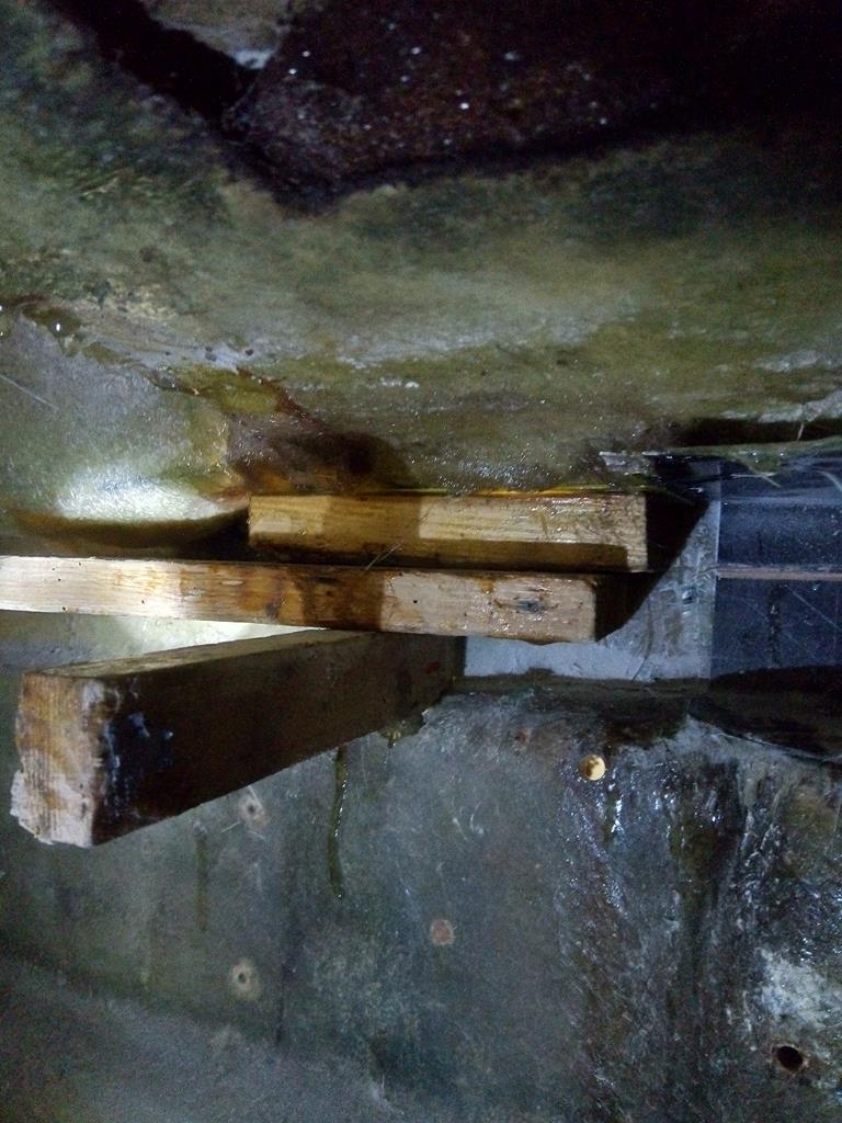
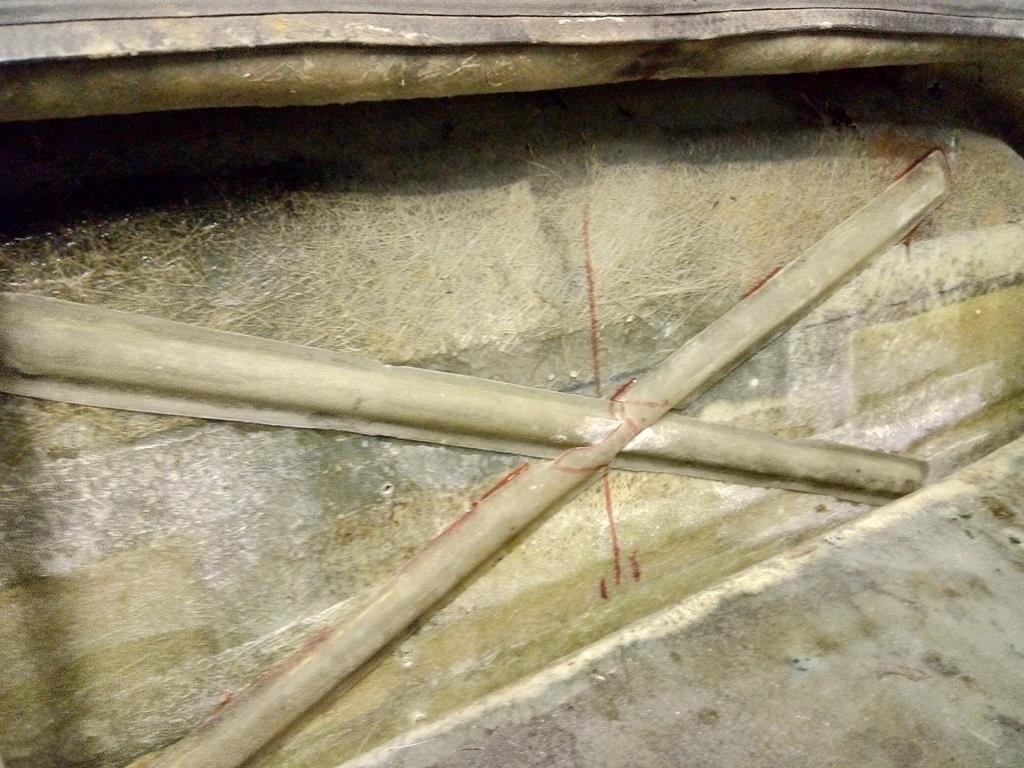
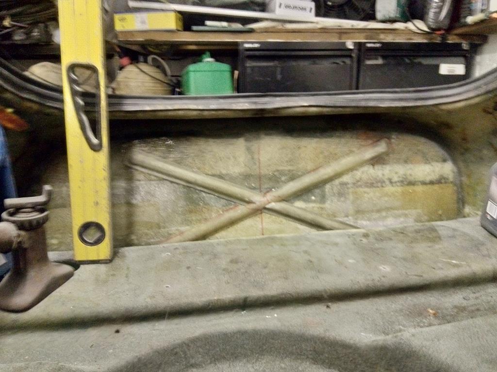
So the beam ends weren't sitting flush with the heel board. But on closer inspection, the heel board angles outward on the top section of the flat panel. I think you can make out the gap. I'll take the beam out and "reprofile" the upper middle mounts so they match the angle to the heel board. The main mounts at the left right ends of the beam should then pull in tight.
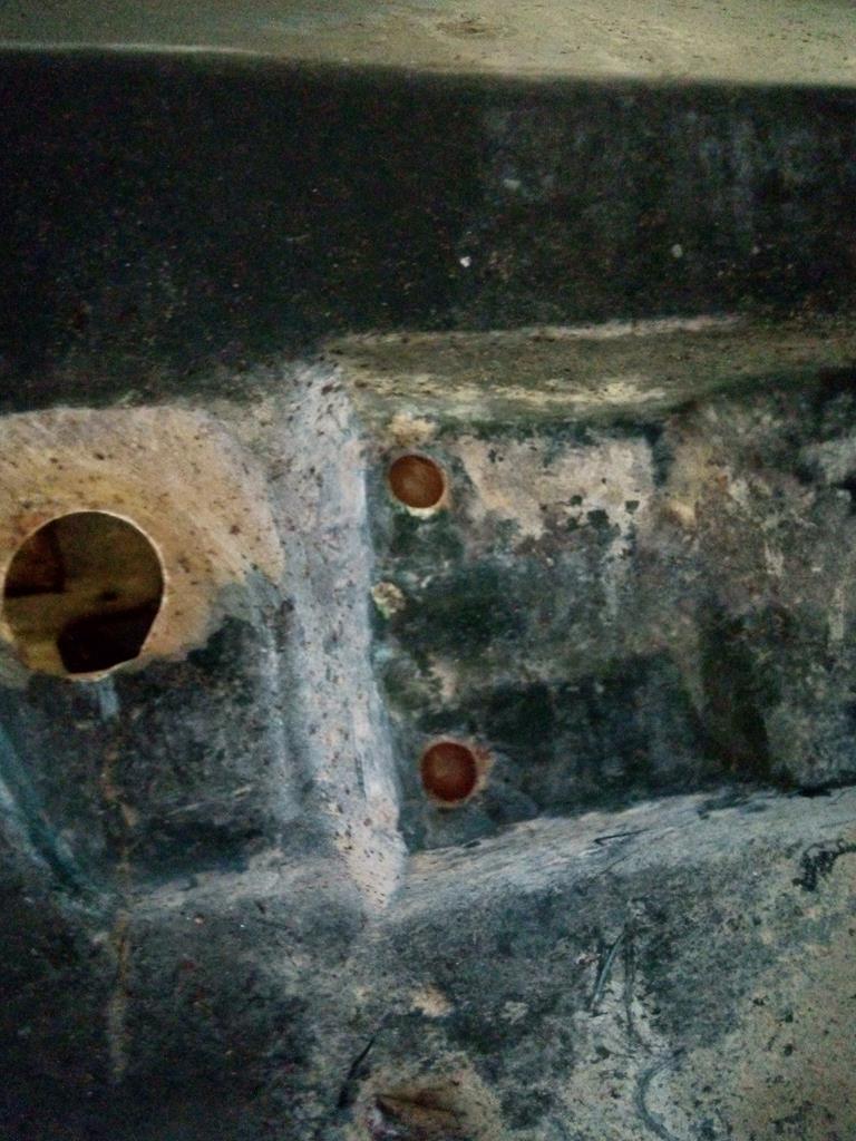
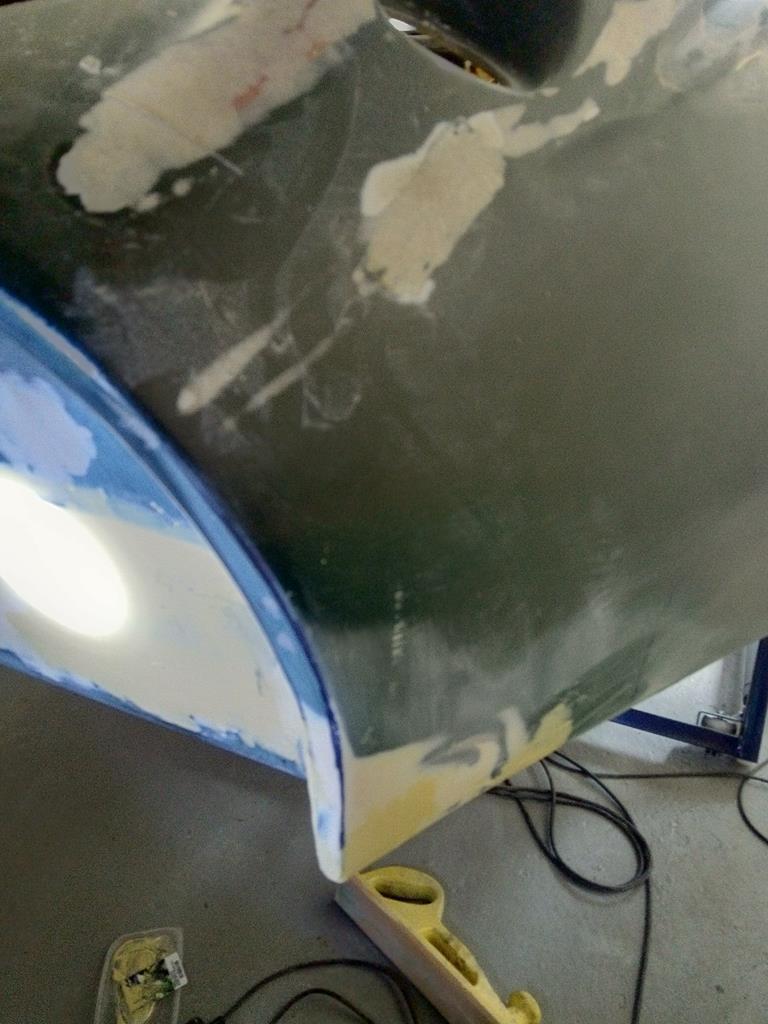
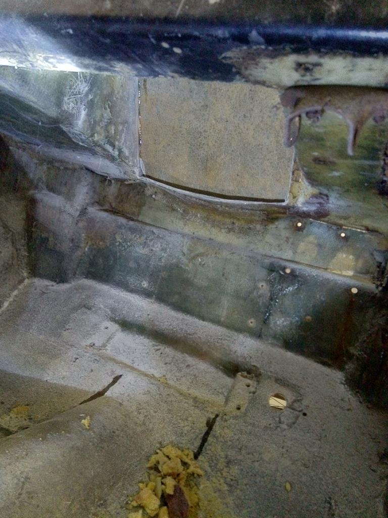
Heel board drilled for the subframe. Took a while to satisfy myself it was lined up. An OCD trigger as these shells are not square. Then a little scuffing, wipe with degreaser then a dust of etch them some left over white primer. Top coat later this week
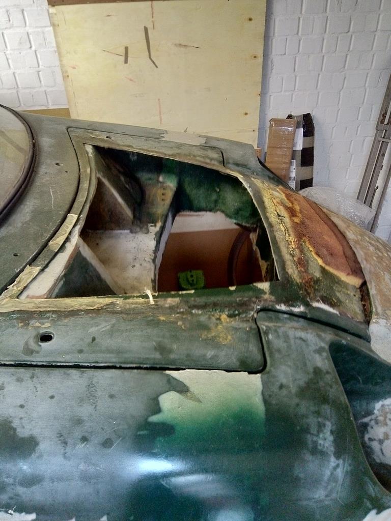
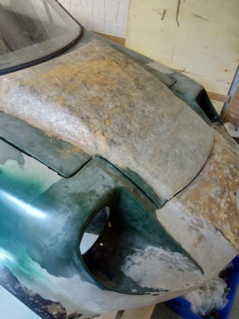
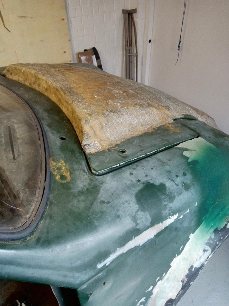
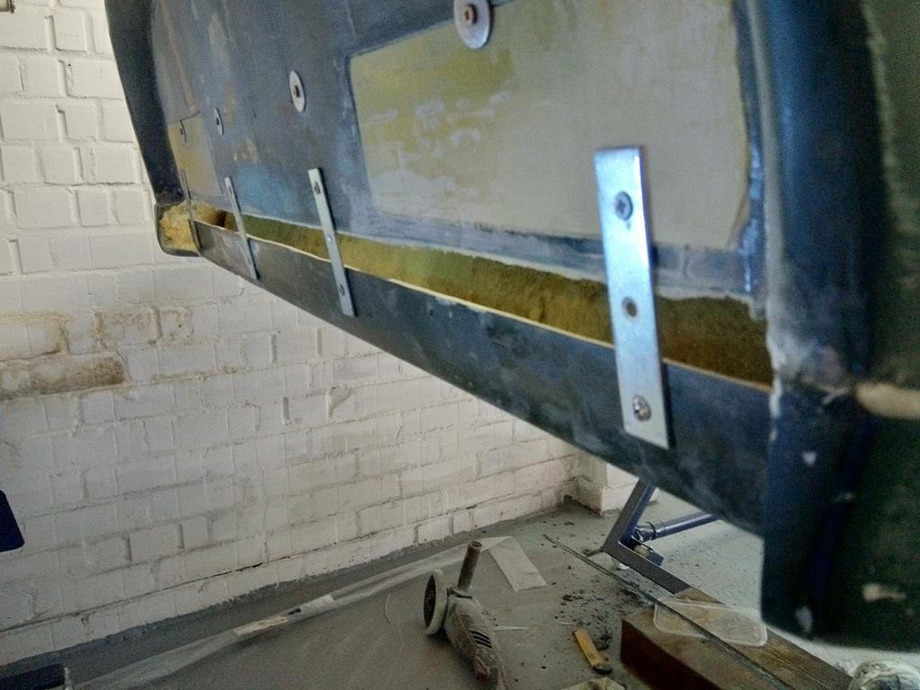
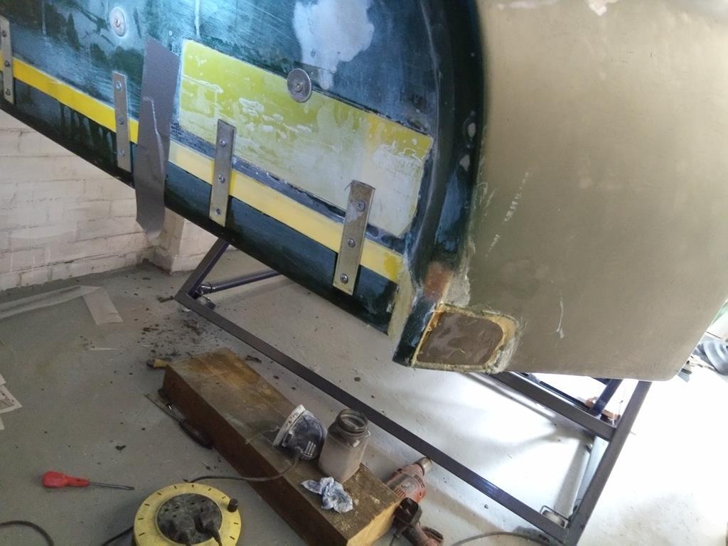
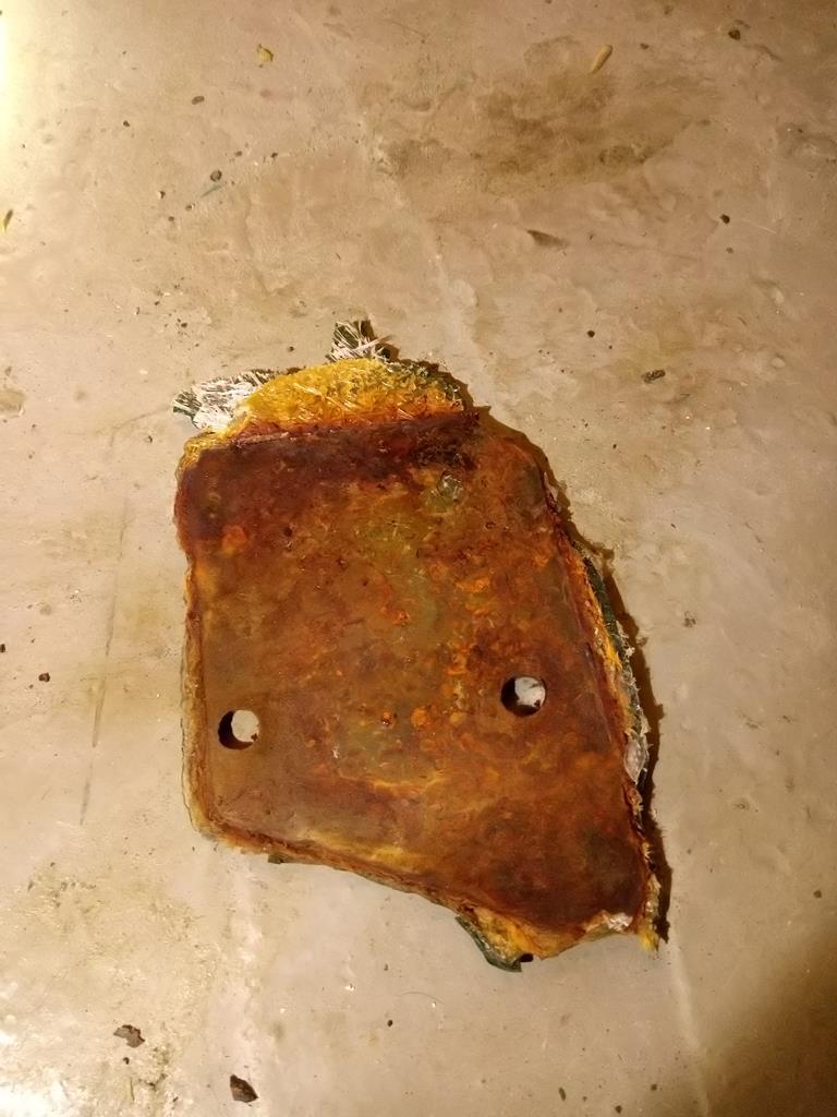
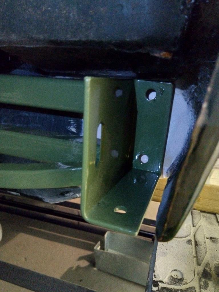
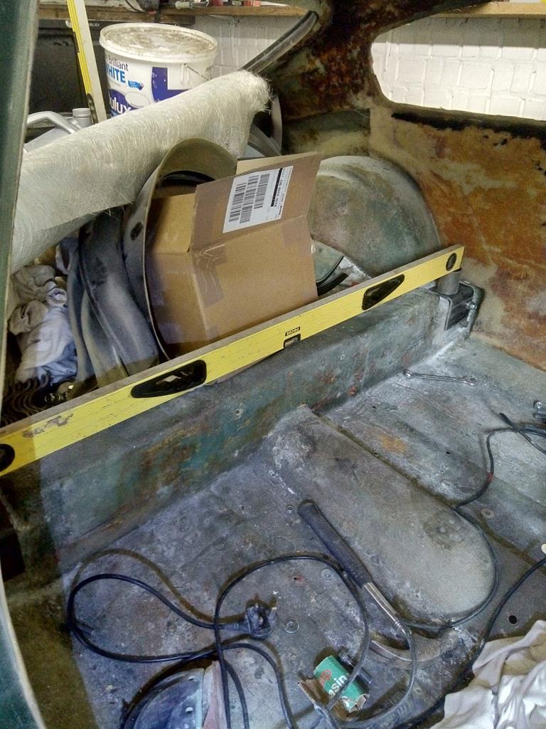
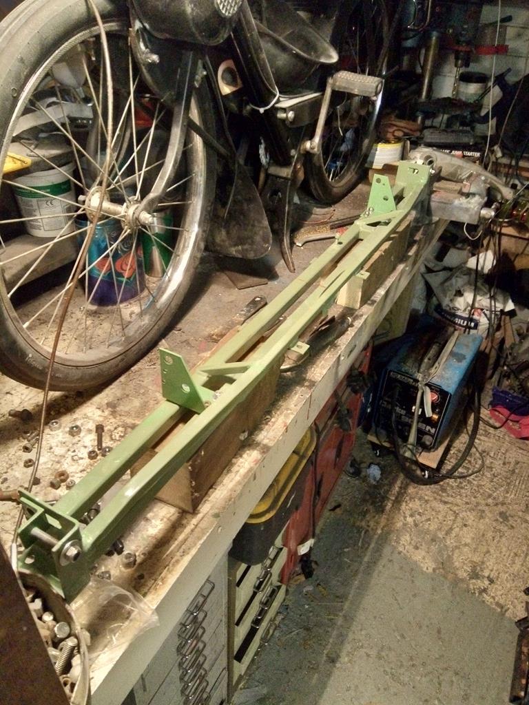
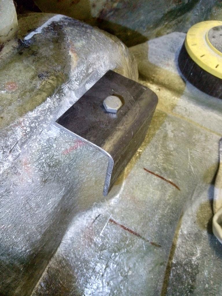
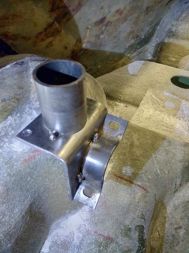
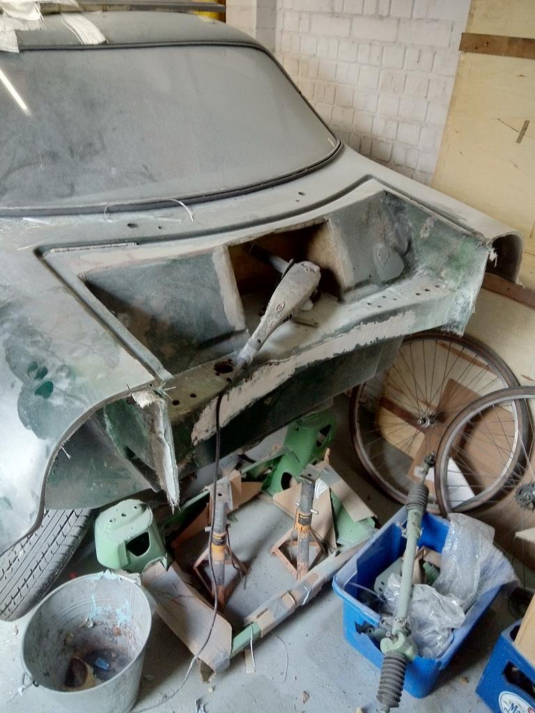
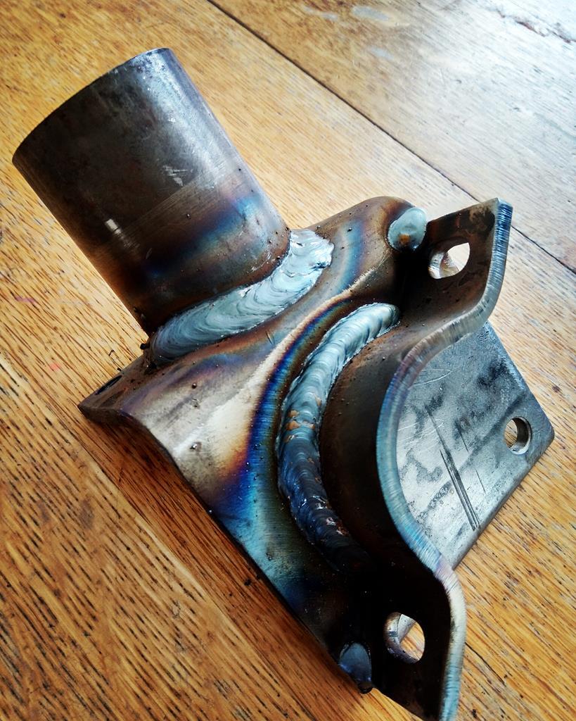
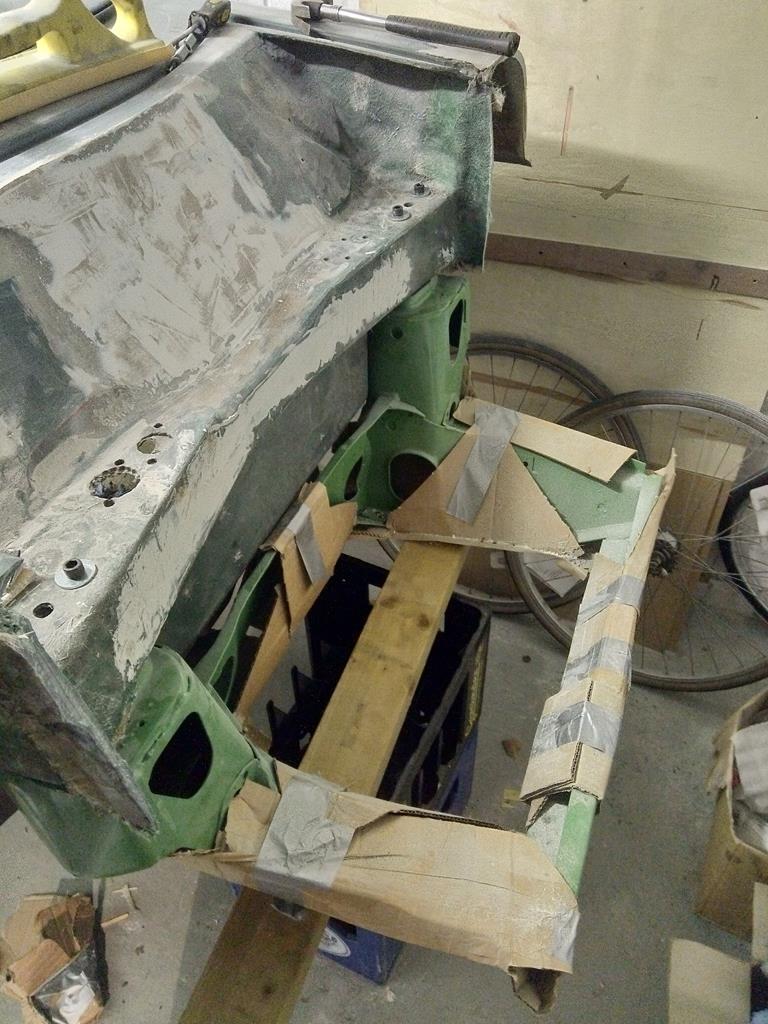
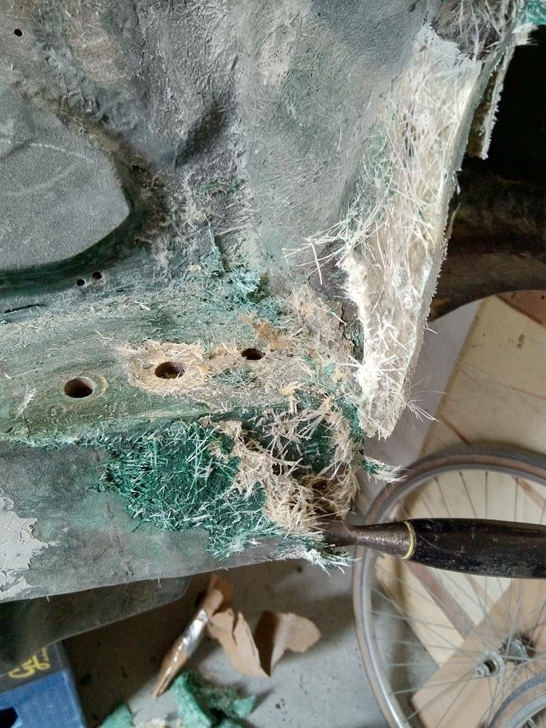
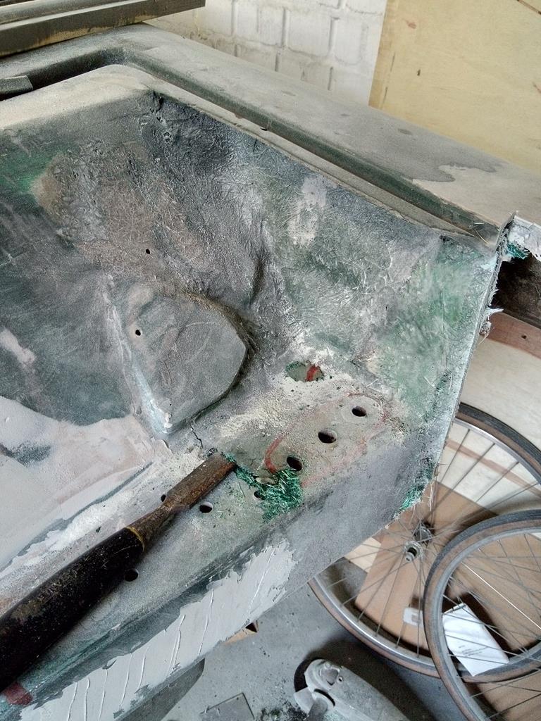
Fabricating the feet for the roll hoop/spaceframe and doing some fit and finish to the heel board surface as it was a bit uneven. The feet pick up the rear subframe mounting bolts that come through the heel board.
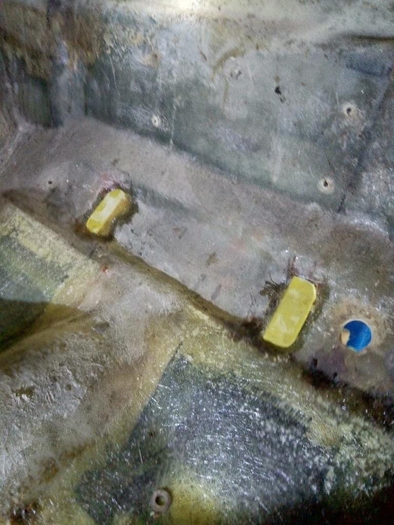
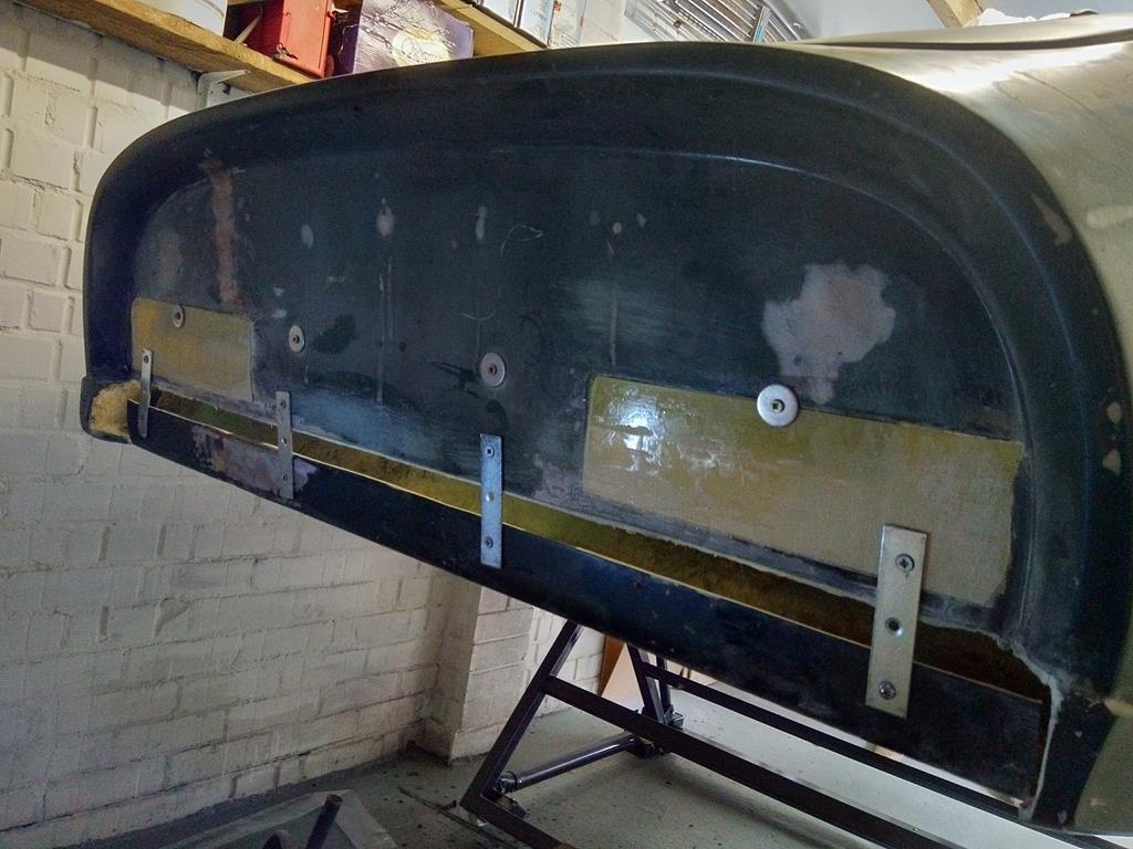
Hoop feet (which also double as strengthening plates for the rear subframe finally in place. Took a while to get them to sit square and level as the grp was uneven (as I'd repaired and rebuilt those areas). Final job will be to lay in a thin layer of CSM and bolt them in, so the metal has a perfectly flat bed.
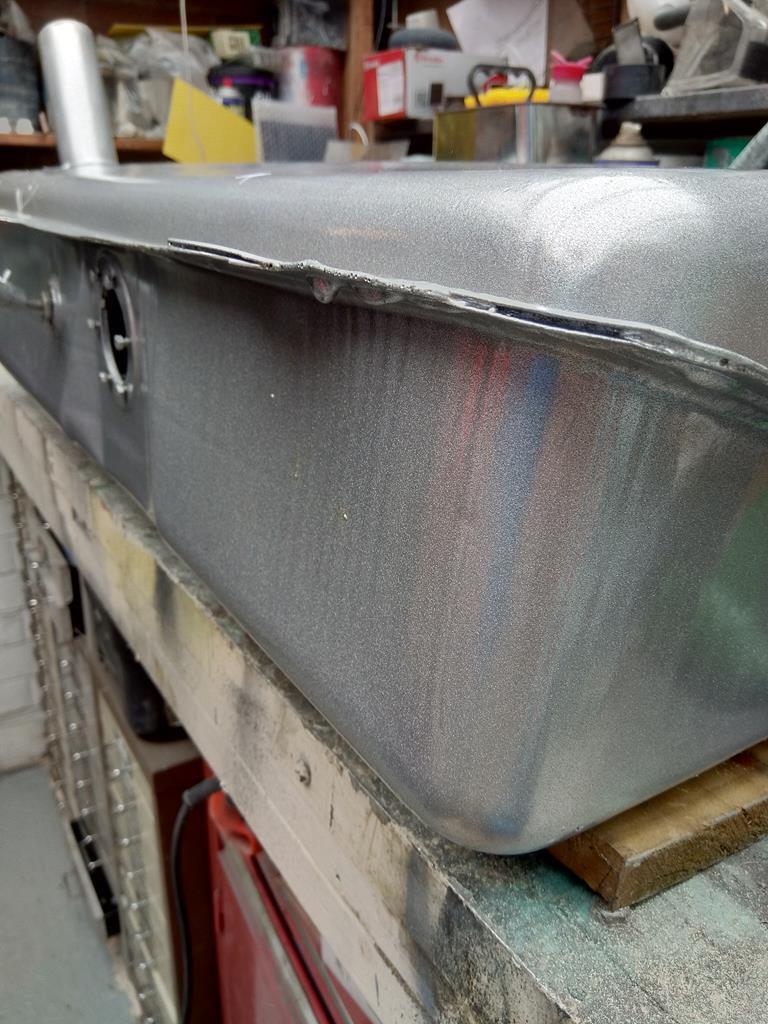
Thin first coat rolled on tonight. I'll leave this for a few weeks then give it another coat.
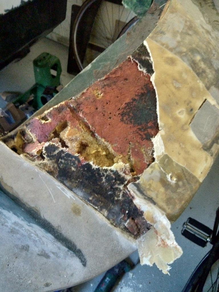
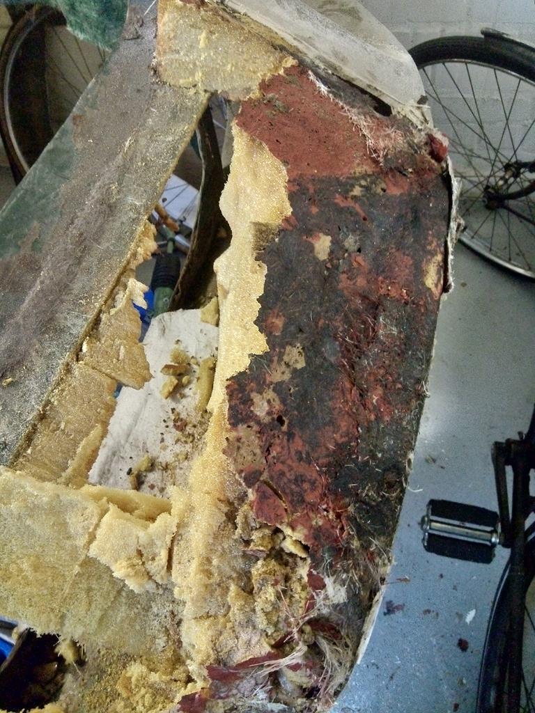
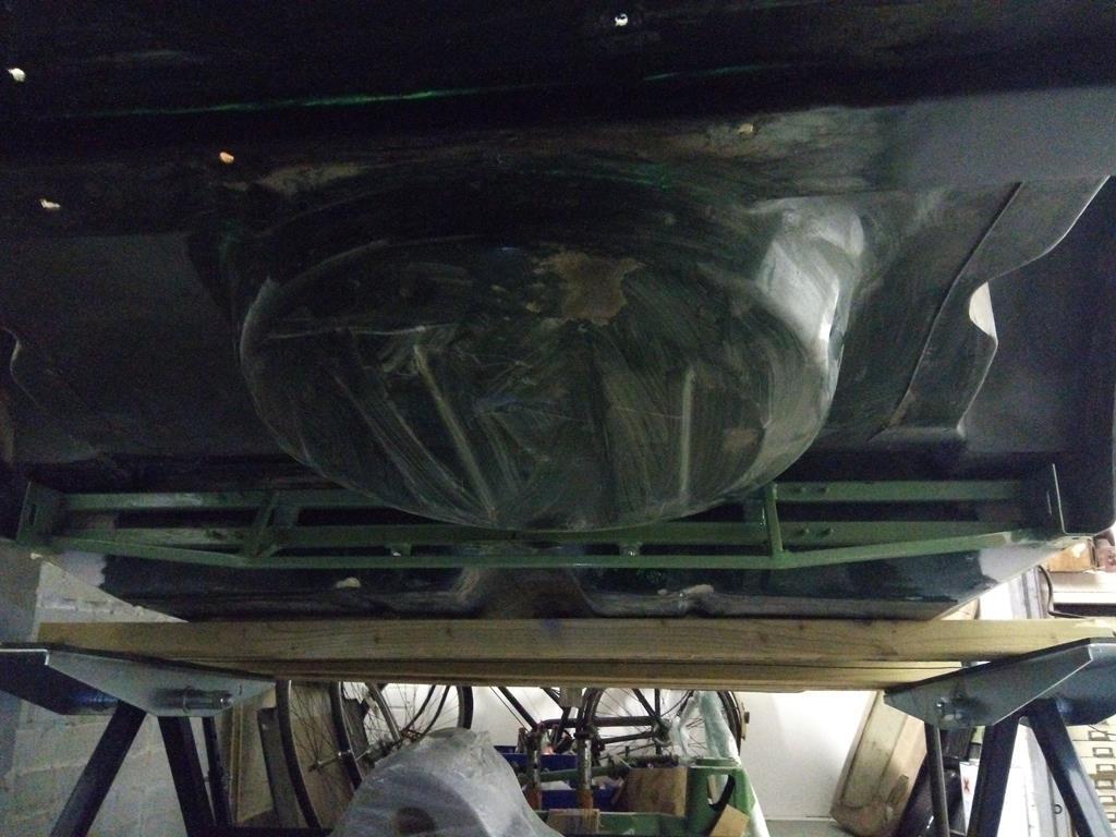
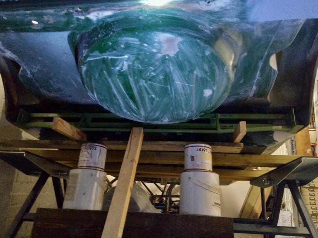
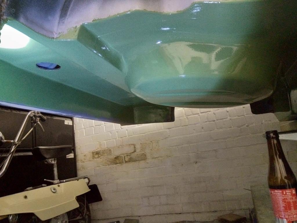
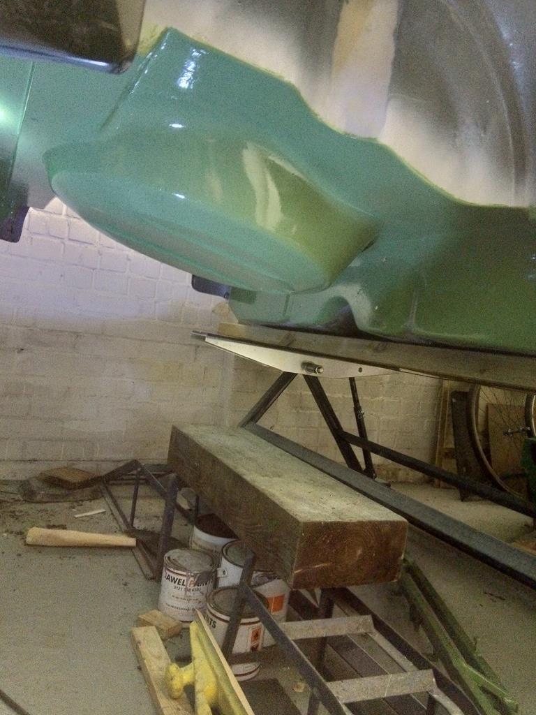
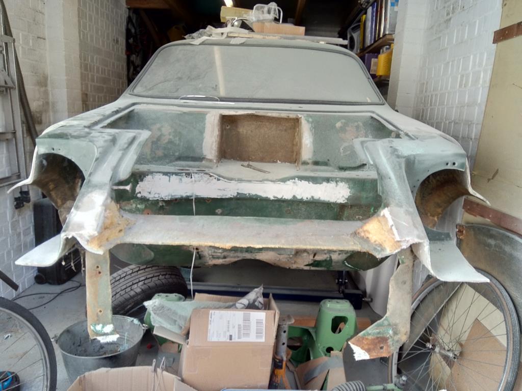
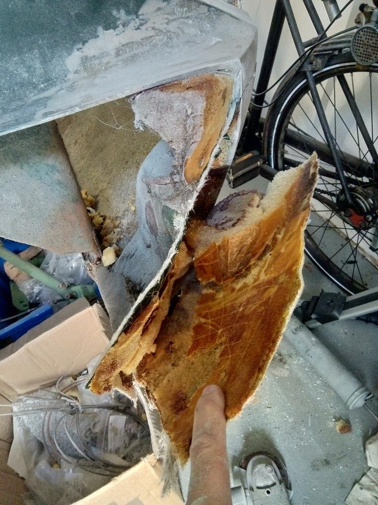
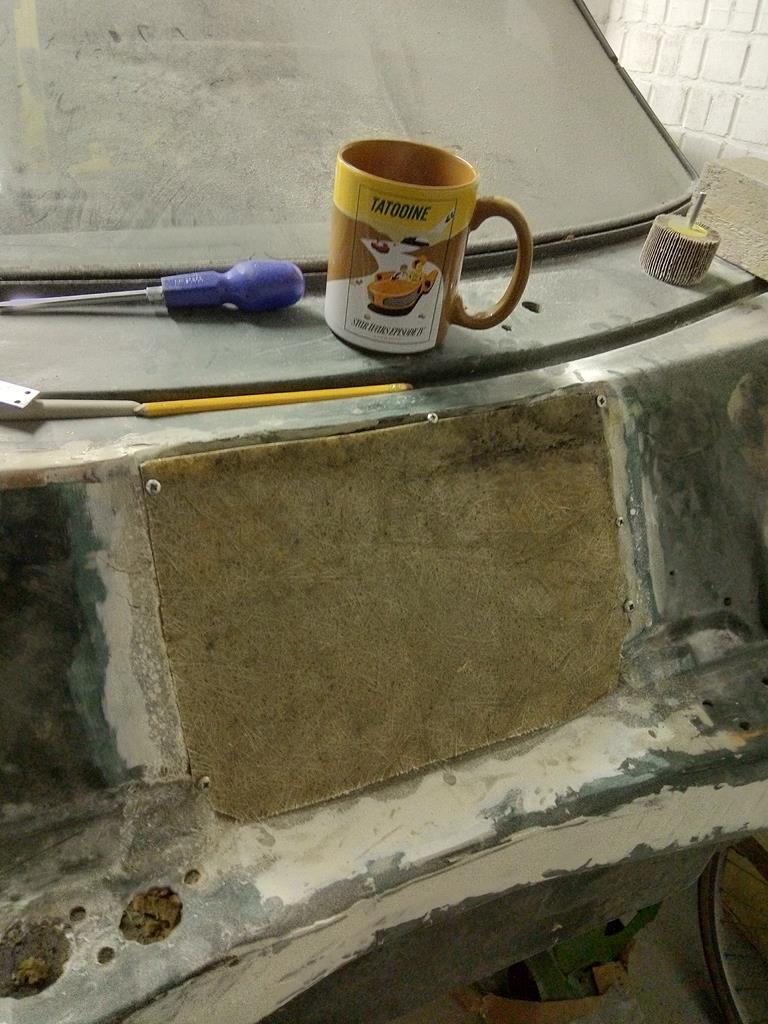
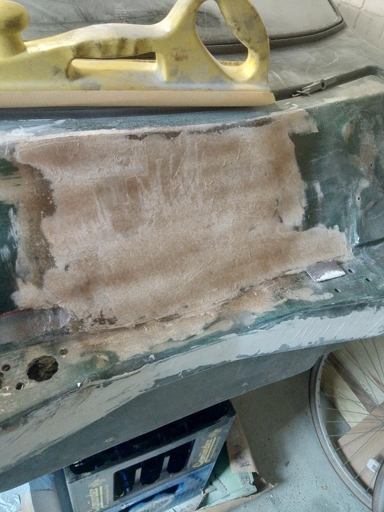
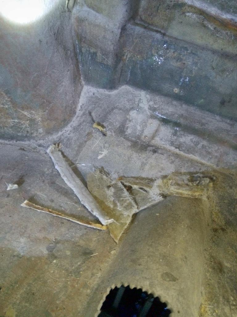
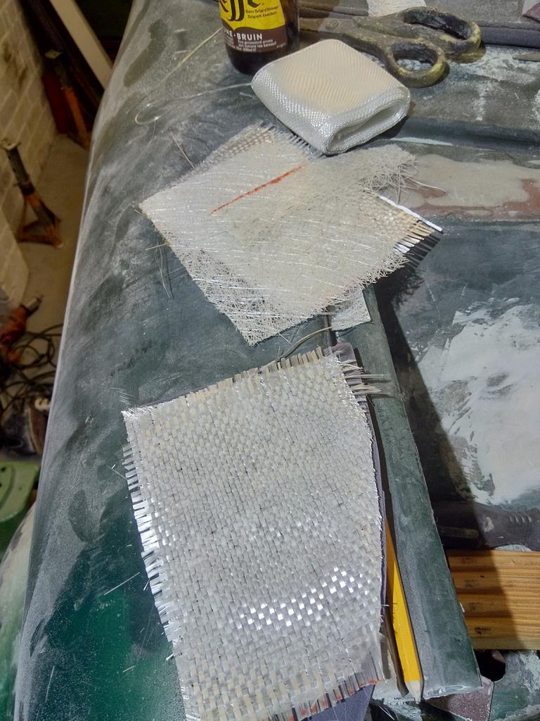
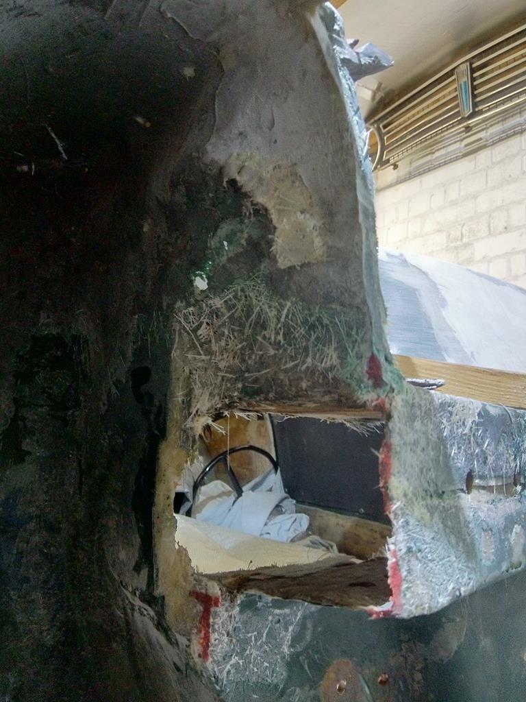
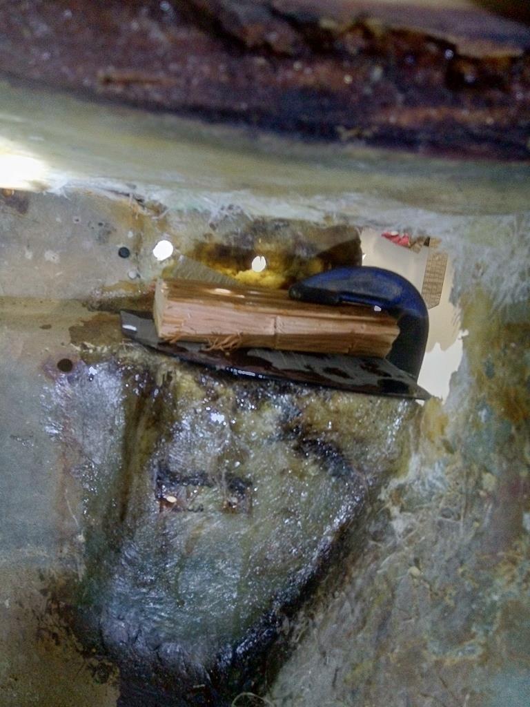
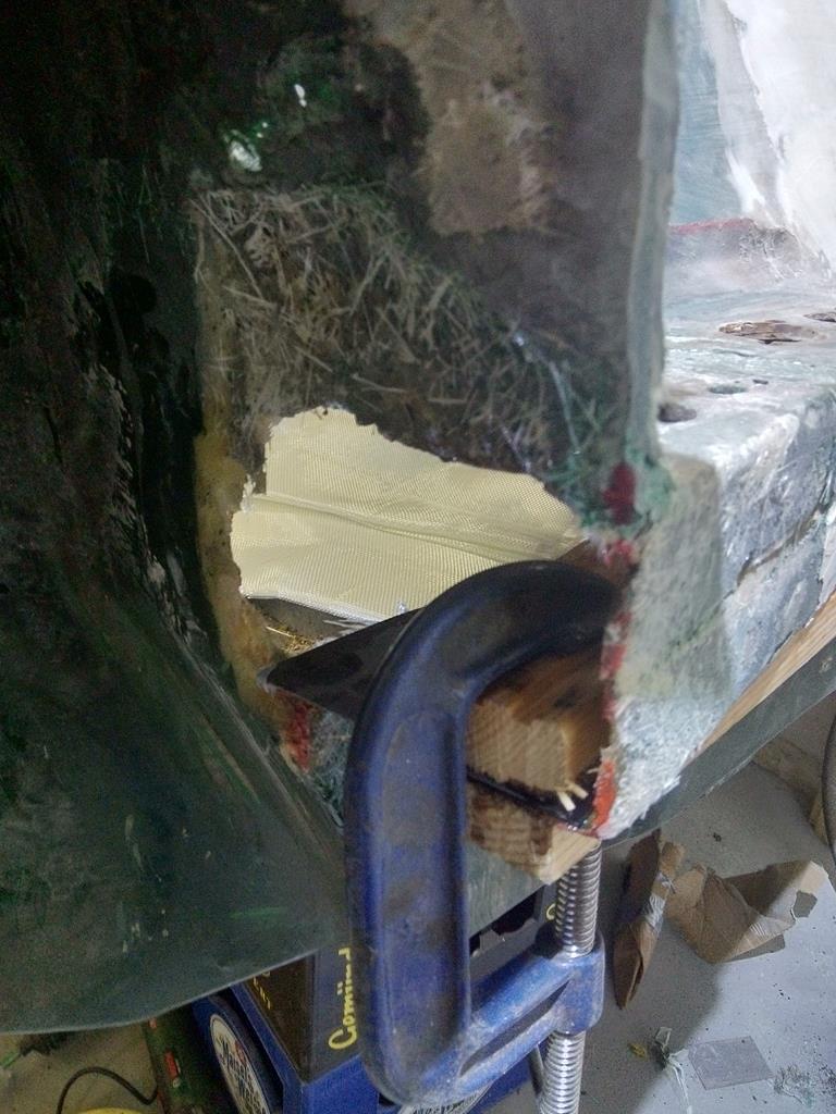
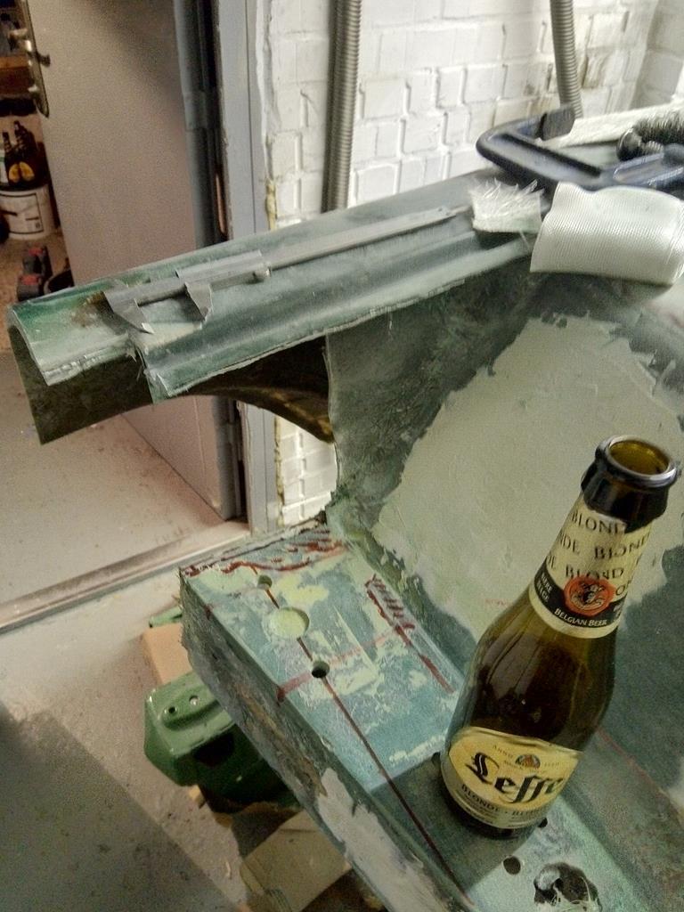
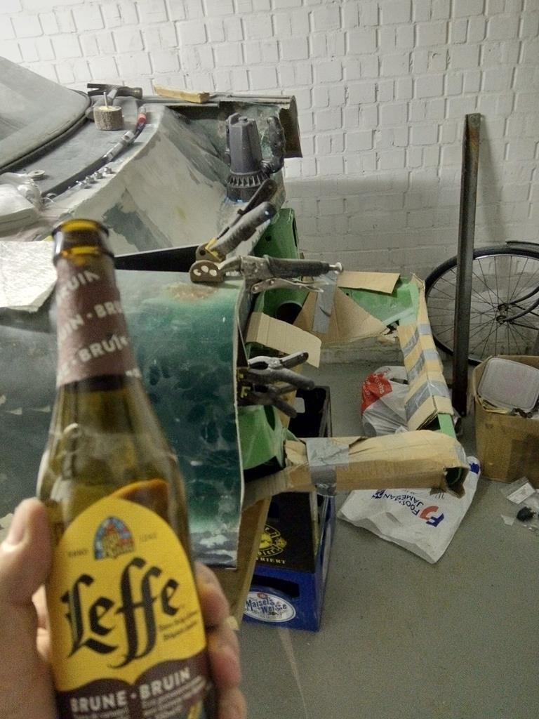
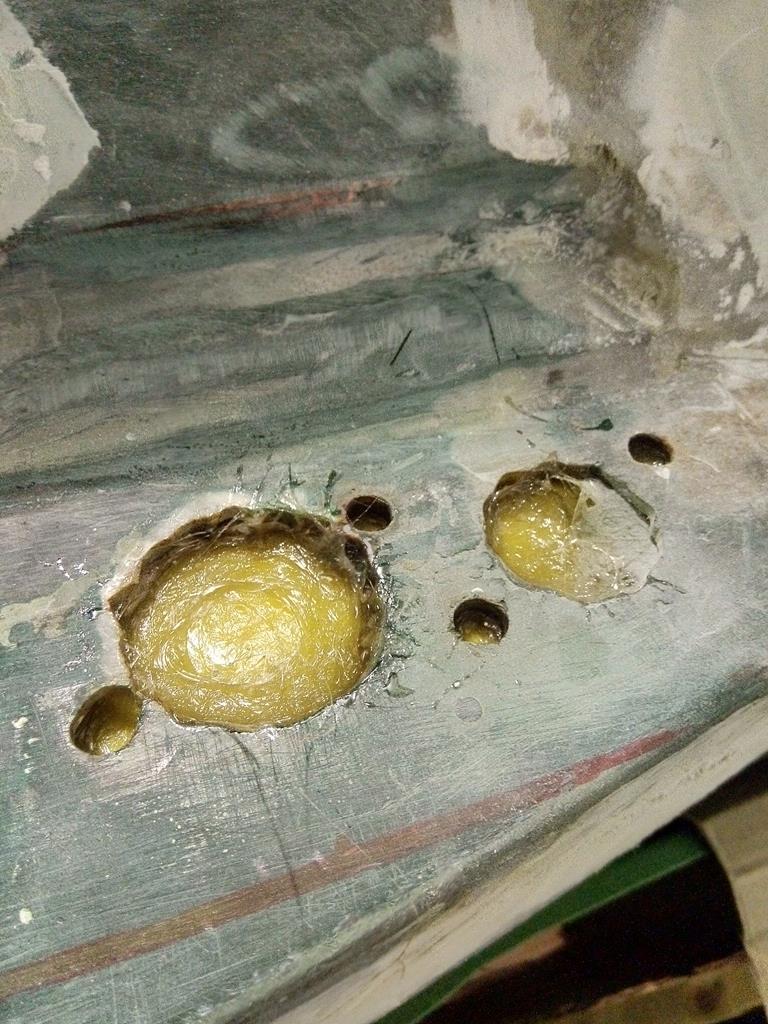
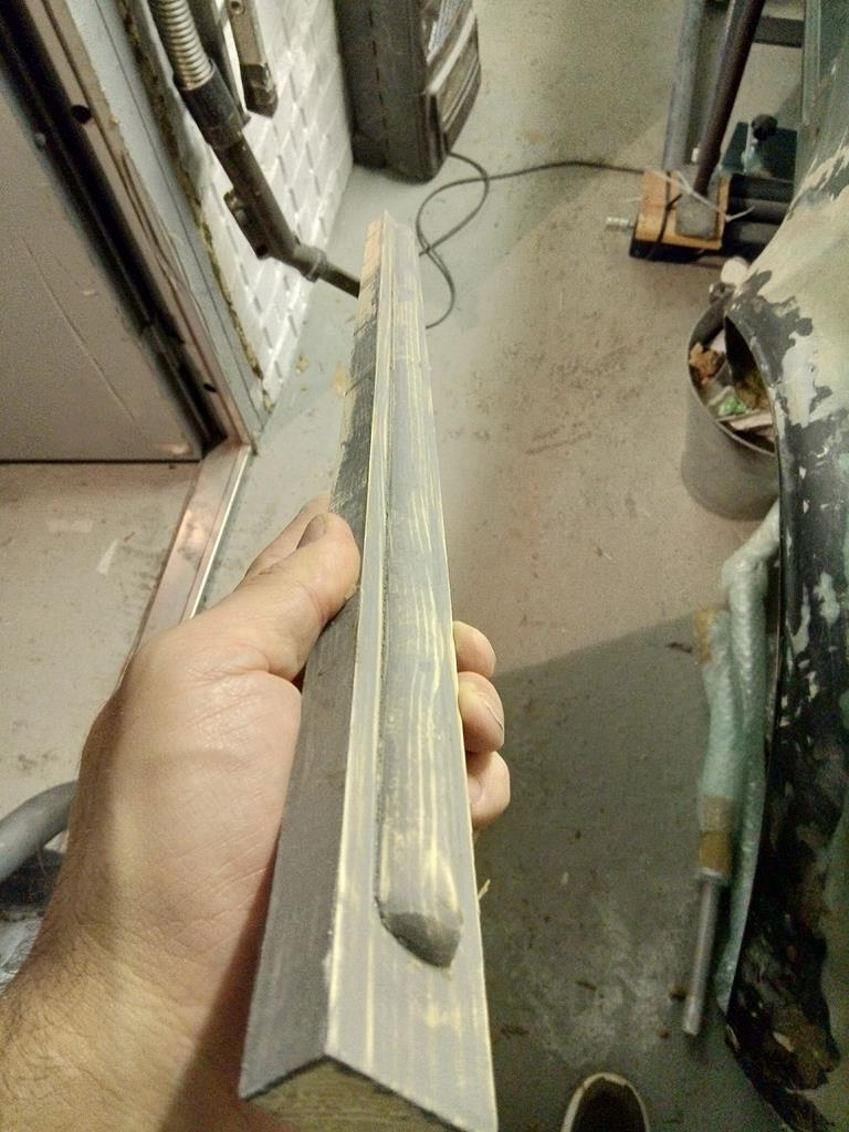
Needed to put some stiffeners in the rear panel as its flexes in the middle. Fabbed a crude mould with a quids worth of offcuts from my local hardware shop. cover it in wide sellotape and coat on some carnuba wax to help it release. 3 layers of glass tissue get one these. Marked up the panel and glued them in with epoxy then will lay over the whole panel some woven roving and CSM. For stiffening but also to make that panel nicer to look at as its got some naff glass work from a PO and also all the repair work where i had to patch up the holes in the panel.
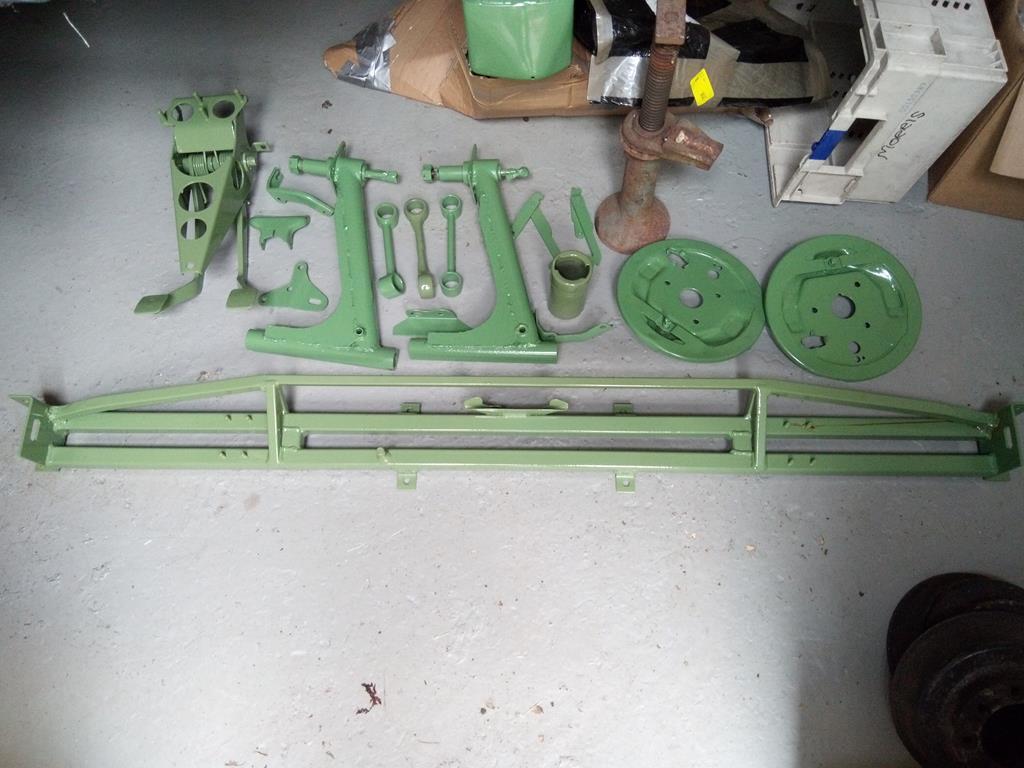
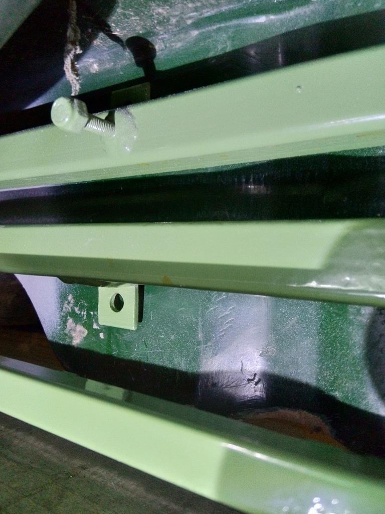
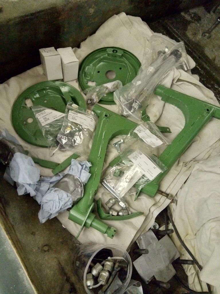
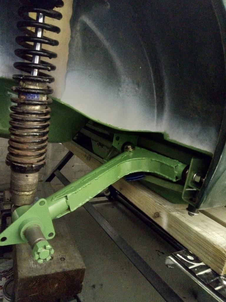
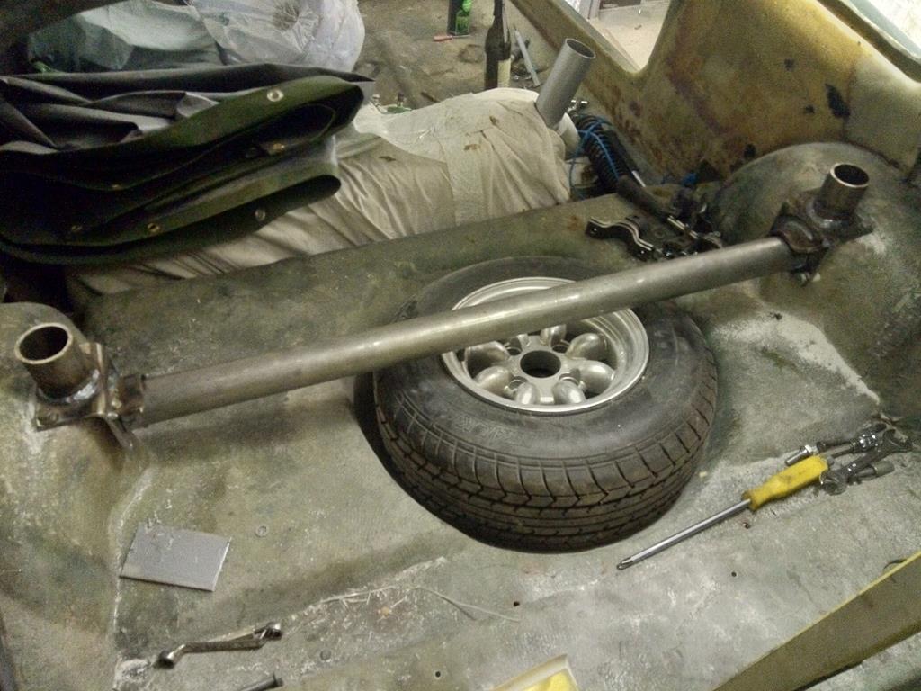
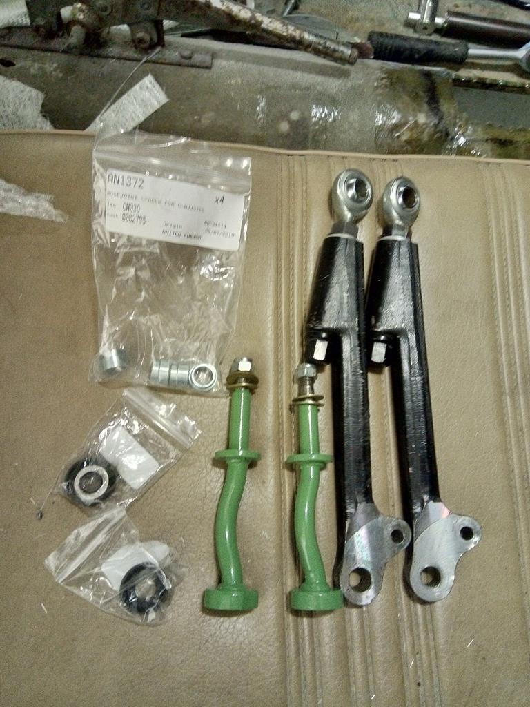
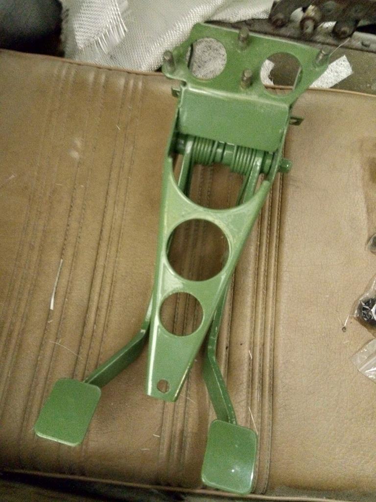
Dug out the bracketry from the powdercoating box and cleaned up the thread to fit them to the subframe. Next up will be refurbing the radius arms and getting those bolted to the subrame. This is so i can get the frame back on the car and bolt up the rear coilovers to check the coilover to chassis clearance. the GAX coilovers have an offset top pin mount but the springs can run close to the inner arch. With the coilover in place, I can fab the spaceframe/rollhoop which i'll send off for seam welding.
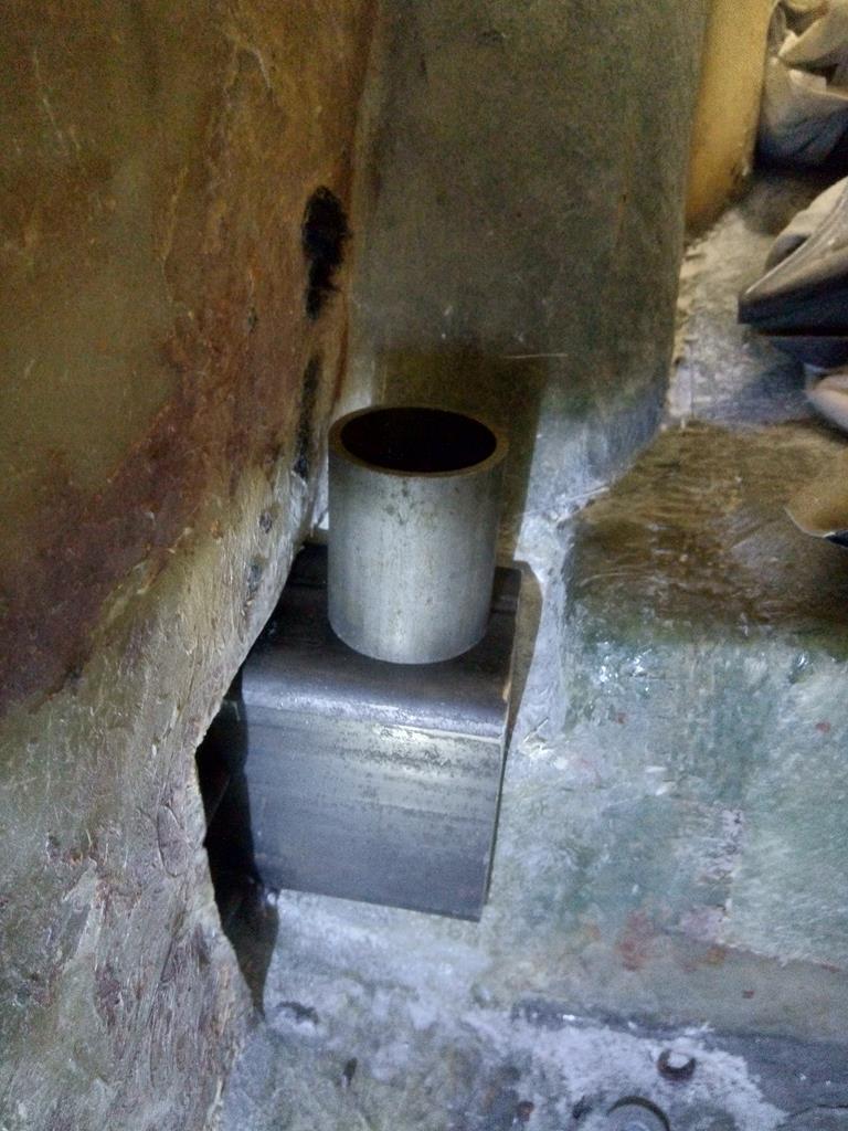
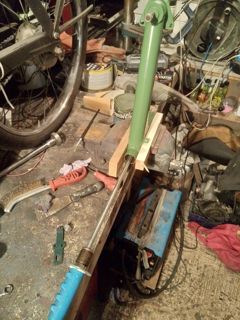
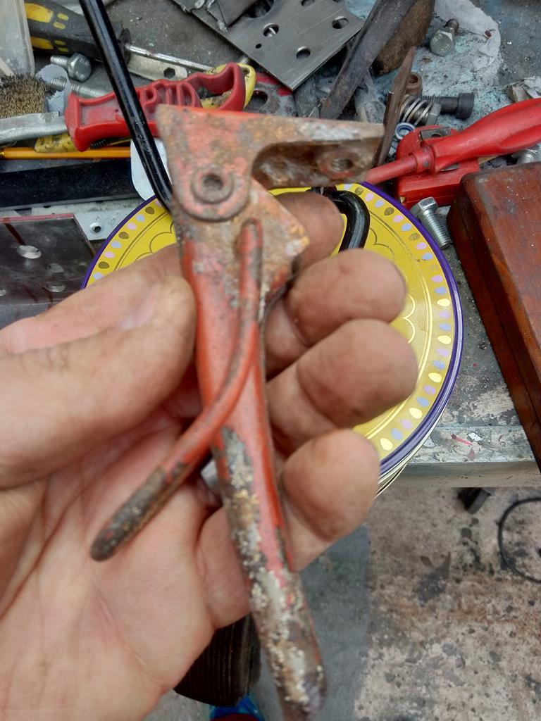
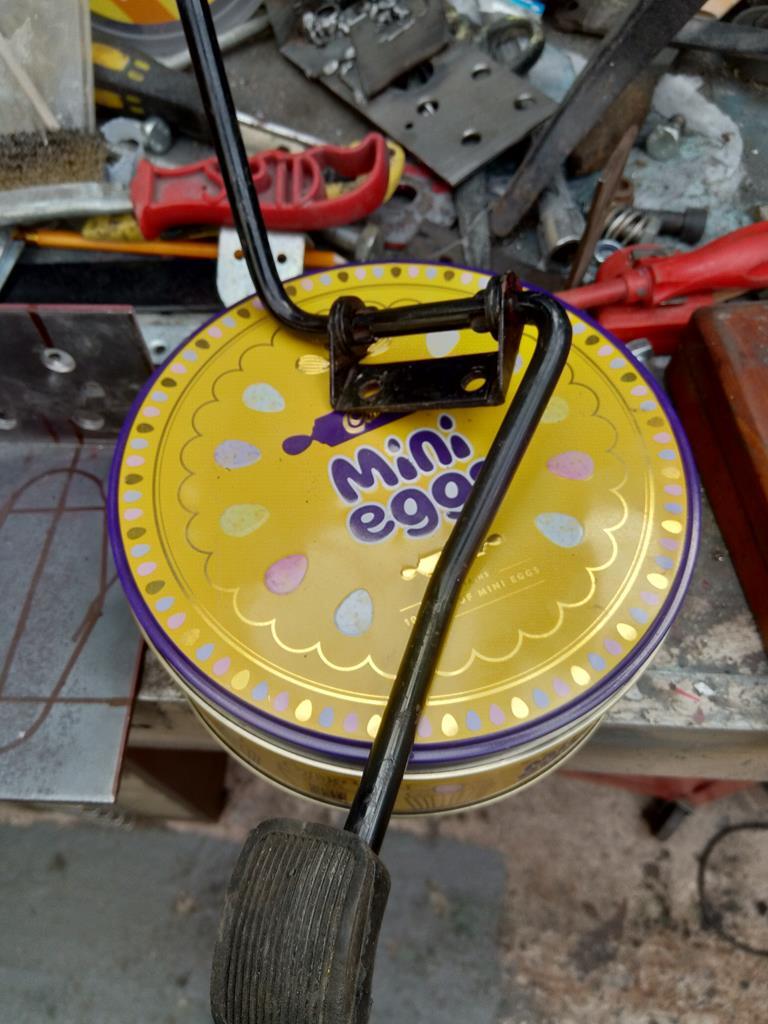
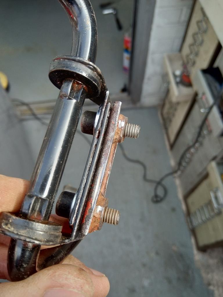
Had to use the modified slide puller to knock out the inner needle bearing which I'd left in when sent for powder coating. New radius arm pin kit fitted, but as this is a custom race arm, it uses a needle bearing at both ends for quick swaps. Normal mini arms have a needle bearing at one end and solid bronze surface Bush at the other (which needs to be reamed)
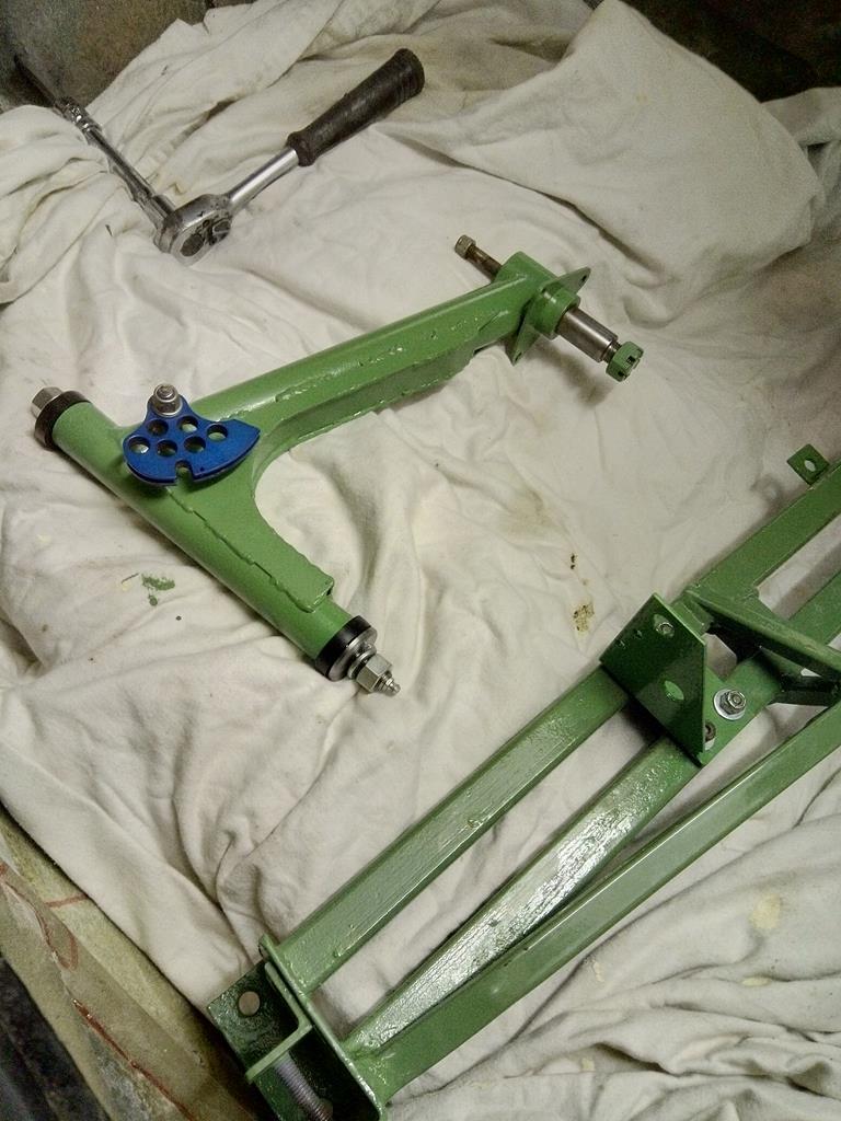
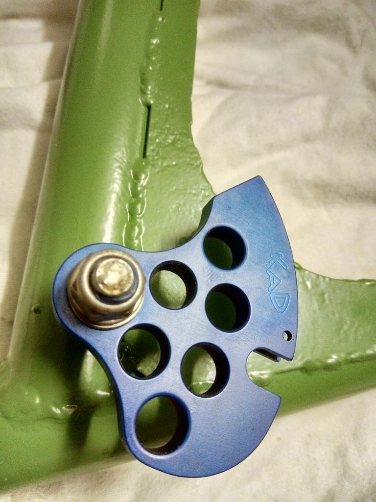
Handbrake quadrant refitted with a new stainless long neck bolt.
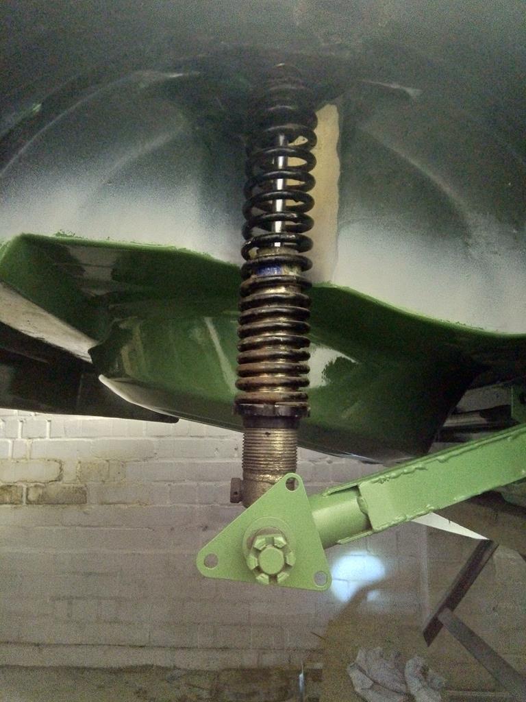
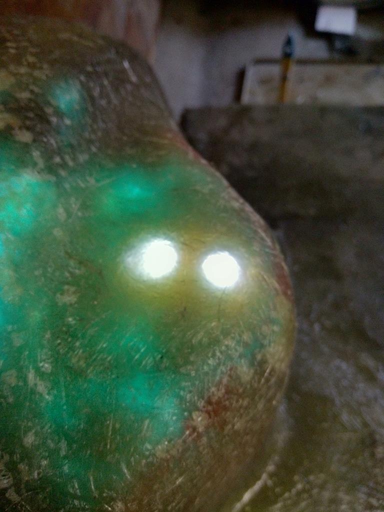
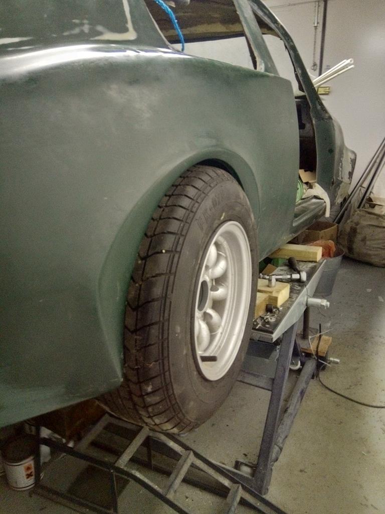
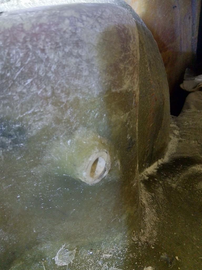
Drivers radius arm bolted in so the coilover could be fitted. Confirmed that the coilover, using the existing mounting hole, is not perfectly vertical. Top mounting hole will need to move inwards so I'll have to fabricate some grp box section to turret the arches.
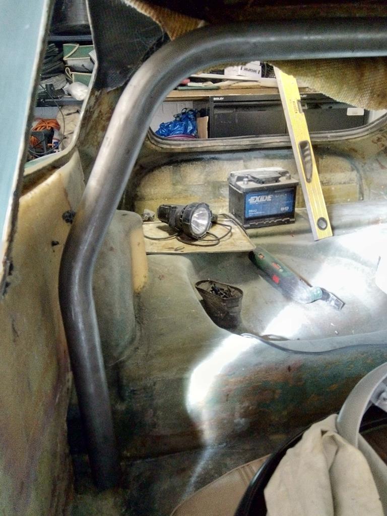
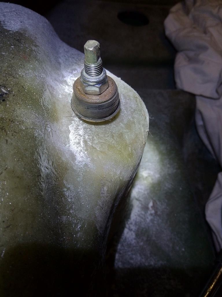
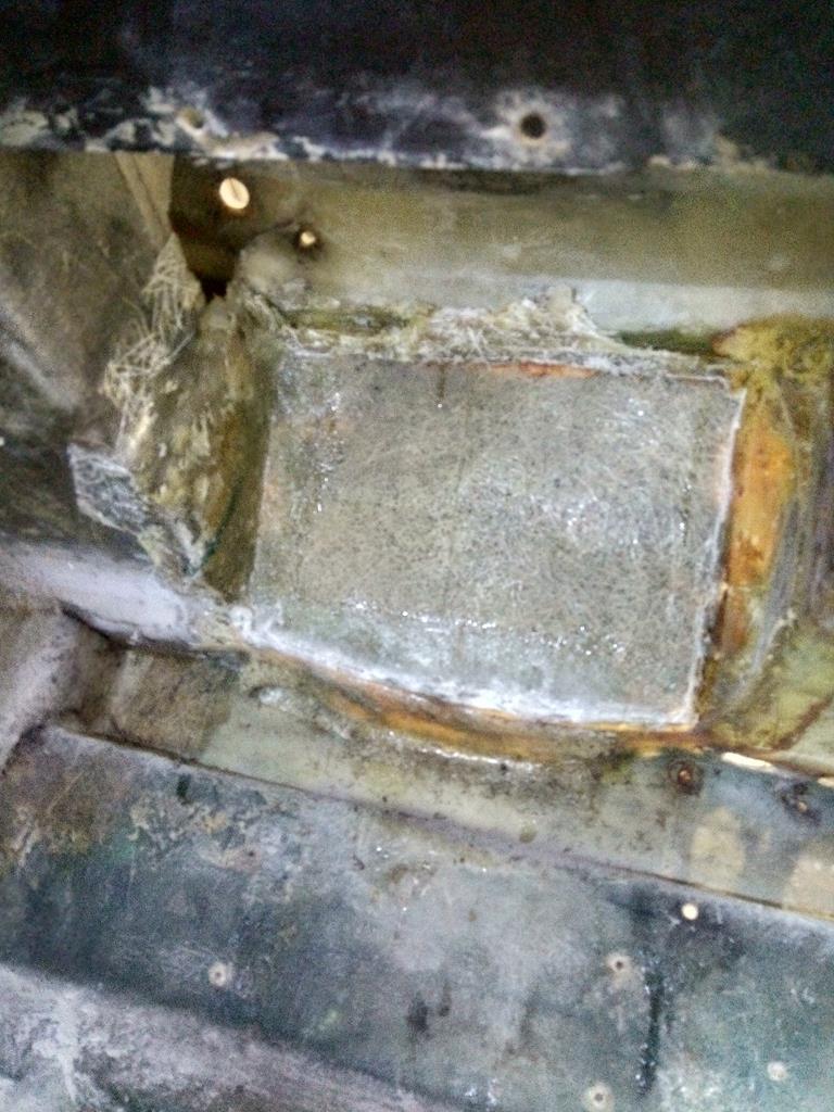
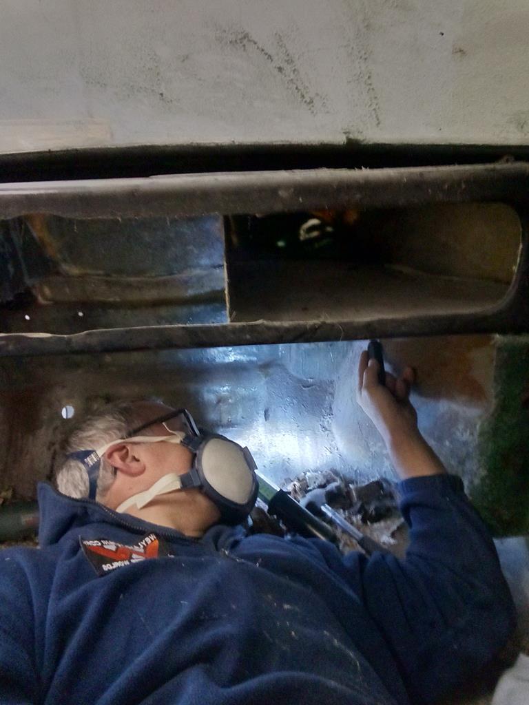
This is the coilover topmount from inside the cabin. Bolted in using the existing hole, which confirms my suspicion that the hole is too far out. Hole needs to move about 10mm to the right. But the coilover will be right into the arch skin.
After reviewing the other rear arch, I've decided it doesn't need turreting. The drivers side is slightly out of tolerance (as you expect for a grp shell). I've redrilled the arches for the damper top pin and they run close (just like a steel mini shell), just that the drivers side is a few mm tighter. That can be sorted with a bit of grinding back (seems that has already been done by a PO)
So first steps was to add a few layers of csm and woven on the inside/cabin side of the arches , just to beef up the arches. Then make the steel brackets for the spaceframe.
My small welder is struggling with the thick steel so hoping the tacks will hold
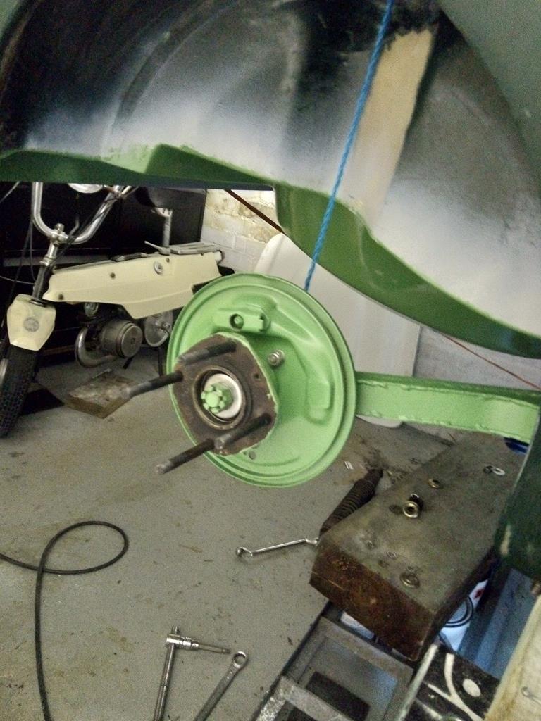
Rear hubs going back together.
#21
Posted 05 May 2020 - 10:07 AM
Put the drum on to see what it looks like
#22
Posted 05 May 2020 - 10:08 AM
Choppy chop......been gagging to cut this front off for ages....what a wobbed up mess, really heavy with all the wag. The expanding foam inside the glass was still damp despite being in the garage for months.
With better access now, I'll start making good the main front subframe bulkhead mounts. Spoke to a wise grp man with minimarcos experience who advised I can rebuild with grp - steel repair ends aren't necessary.
#23
Posted 05 May 2020 - 10:12 AM
First batch of welding back from intergalactic Wayne who has awesome glue skillz.
Best check the spare still fits.....just enough room to shuffle in.
Crappy bulkhead airbox be gone! Took the decision to get rid as it was just another bit of dodgy fibreglassing. Will replace with a smooth bulkhead.
Random bit of flat-ish grp glued and screwed in. This will be glassed in from the back then given a couple of layers of tissue to smooth out the top layer. Then a skim/sand for blending in. As much of the bulkhead will be smoothed for a clean look. Unlike a mini, the wiper motor will be in the dash, and I'll run the main loom and fuse box on the cabin side of the bulkhead.
Cut down some grp tubing to make a couple of mounting bosses for the rear coilover mounts. Glued in place then glassed over.
Bulkhead after a few skims of fine filler. Now trying to get the low spots
This is the view from inside the dash, where the airbox was. Chopped out the
remains and will glass in some more CSM to add the strength back.
What fun...offered up the front subframe to see what happens. No surprise it doesn't go smoothly
#24
Posted 05 May 2020 - 10:20 AM
Here we go. Attacking the drivers side subframe top mount, chiseling and peeling away the layers of crappy glass. Most of the original outer gel coat structure is intact under the crap.The metal has rotted away and the PO has hammered in a wooden block. No metal for the shock absorber mounting though which is concerning. I really have no idea what the PO was trying to do.
#25
Posted 05 May 2020 - 10:21 AM
Chiselling out the drivers side bulkhead mounts (remains there of)
#26
Posted 05 May 2020 - 10:24 AM
I worked out that the PO had spend loads of time and money to bodge repair the shell. They left rotten metal mounts in situ and fitted some shaped wood around the crush tubes. Then glassed it all back together. The work involved was almost the same as doing a proper repair.
This red stuff hadn't gone off. Thinks it's fibreglass filler
Chunk of the shaped wood to fit around the crush tubes
This is the passenger side mount after chopping out the crappy glass. The wood fell apart.
#27
Posted 05 May 2020 - 10:26 AM
Cleaning up the passenger side bulkhead. About the same mess as the drivers side.
Weapon of choice a very sharp wood chisel to separate/split off the dodgy fibreglass.
Waiting on some parts to arrive so I can finish off the bulkhead mounts. Therefore got on with some other jobs. First off, ordered more garage beer. Out of the 2 crates of wheat beer that my man @chasr drove to Germany to get and down to my last 2 bottles of leffe that came from beerhawk.
Dug out the throttle pedal and offered it up. Ideally needs some captive nuts in the bulkhead as there's no much room behind the subframe. Rooted through the scrap box and found this old over centre clip. No idea where it came from. Captive nuts were perfectly spaced so zipped em off with the cutter. Plate will be glassed in eventually.
Current state of play with the drivers front coilover/subframe mount.
#28
Posted 05 May 2020 - 10:26 AM
Got the frame bolted in. Had to fettle the 4 top bolt holes and had to use a circular abrasive grinder thingy to make a 2mm relief on the underside, so the frame pulls up tight. Now the bolt holes are confirmed, I can mark up the top metal bracketry for drilling, and can drill the bolt holes for the lower subframe mounts (through the floor).
#29
Posted 05 May 2020 - 10:27 AM
Dug out the adjustable bottom arms to check I'd got all the bits. Note to self must clean off the powdercoating on the pin contact surface.
#30
Posted 05 May 2020 - 10:27 AM
Occurred to me I couldn't bolt up the accelerator pedal as 1) the holes looked on the wonk (curse of the PO again) and 2) needed to check reference against the pedal box.
Dug out the pedal box but had to clean off the powder on the bolt threads and retap. Offered it up and location was good but the mounting surface going through the bulkhead was a bit thin, uneven and generally iffy. Cut a section of flat grp sheet plate and wedged it in with a few layers of glass/resin to go off overnight.
0 user(s) are reading this topic
0 members, 0 guests, 0 anonymous users