Jump to content


Photo
- - - - -

Airbox Design For Specialist Components Efi Kit


  • Please log in to reply
6 replies to this topic

#1 fokko

fokko

    Mini Mad

  • TMF+ Member
  • PipPipPipPip
  • 191 posts
  • Location: The Netherlands
  • Local Club: Mini Seven Club Nederland

Posted Yesterday, 09:09 PM

I am designing an airbox for the Specialist Components EFI kit (I bought it as a replacement for my HIF44). I have two simple reasons:

  • Reduce induction noise in the cabin
  • Have cold air enter the engine

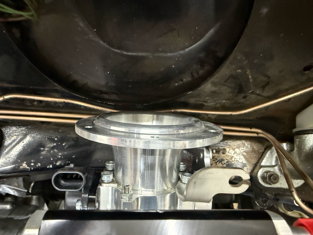
The factory setup is as follows: the throttle body has a trumpet, which has a flange with threaded holes. The airfilter backplate is mounted to this flange by screws that go into the treaded holes of the flange. The foam ITG filter is then mounted to the backplate using a clamping mechanism. As discussed, this will be removed, which leaves me with the flange.
 
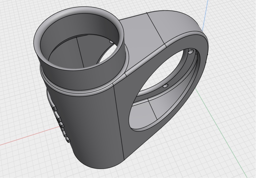
I designed an airbox with a 51mm inlet (my throttle body is 45mm), that mounts to the flange. Mounting it is the real challenge, also because of the lack of space. I considered several options:

  • Have an access hole from the back of the airbox (firewall side) that would give access to the screws. The hole would then be closed by a screw-on circular lid. This is my current test design and I already discovered that mounting the screws is a real challenge due to lack of space and angle at which the allen key needs to be held.
  • Screws that go completely through the airbox from the backside with a support tube. That has two potential downsides: bad access and obstruction of airflow.
  • Bore out the threads in the flange, create hexagonal spaces in the airbox to put nuts at the inside of the ring that faces the flange of the trumpet, screw from the outside (throttle body side).

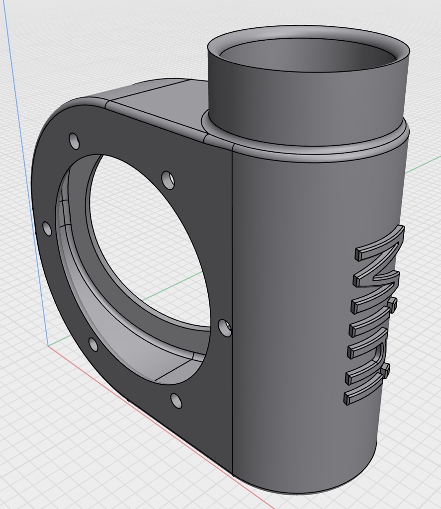
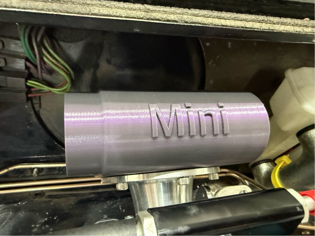
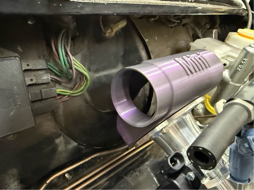
I provided pictures below of my latest prototype.


I need help! Does anyone have clever ideas on how to improve, other than the ideas I listed above?


Note: the screws in the picture are inside of the metal thread of the flange and just hold the airbox in place because it hangs on the screws. Don’t think I already fixed it ;-).


Also: the Mini name on the airbox will improve and match the actual font/style. This was just a test to see if I could emboss letters. I’m still a novice with 3d design…

IMG_0002.JPG

IMG_0003.JPG

IMG_0004.JPG

IMG_0000.JPG

IMG_0001.JPG


Edited by fokko, Today, 08:17 AM.


#2 fokko

fokko

    Mini Mad

  • TMF+ Member
  • PipPipPipPip
  • 191 posts
  • Location: The Netherlands
  • Local Club: Mini Seven Club Nederland

Posted Today, 08:16 AM

To be clear, I'm asking for help here. Not sure if people viewing note my actual question: do you have ideas on how to mount this thing so it can be easily removed? ;D


#3 stuart bowes

stuart bowes

    Up Into Fourth

  • TMF+ Member
  • PipPipPipPipPipPipPipPipPip
  • 2,560 posts
  • Location: Dagenham

Posted Today, 09:34 AM

longer studs, so they go right through and out the other side, then wingnuts?  I can't see that affecting air flow to any noticeable amount to be honest, I've had 'real' airboxes that do exactly the same


the 'other side' would need a parallel flat though I guess (or a an angled piece you add in under the nut, or the 'lid' piece shaped accordingly)


how are you manufacturing this just out of curiosity?  is there a ring type filter going in there, or a cone type externally


Edited by stuart bowes, Today, 10:25 AM.


#4 alpder

alpder

    Super Mini Mad

  • Members
  • PipPipPipPipPipPip
  • 565 posts
  • Location: Pembrokeshire
  • Local Club: MCR

Posted Today, 09:38 AM

Looks like a fun project.


I'd experiment by making a test-piece which was just the bottom ring of the 3DP, with printed threaded holes which are one size smaller than the threaded holes in the trumpet. Then you can get a feel for what it would be like to thread screws upwards into the 3DP through (future bored-out) holes in the trumpet. My guess is, it will be awkward. And would be even more awkward trying to thread the screws upwards into not-quite-captive nuts which stand a chance of being dislodged and falling into the trumpet.


Aerodynamically, you've got a couple of things going on: the air comes in a 51dia tube, followed by a sudden expansion to what looks like about 150dia then a reduction to 45dia. In general, air flows pretty cleanly through (smooth) reductions, but gets properly turbulent through expansions unless they are extremely gradual. You'll also get a lot of swirl because the inlet is offset - the air will be rapidly rotating in the large space like it's in a cyclone air/dust separator, then by the time it's been squeezed into the reduction that rotation will be amplified into a tornado in the throttle body. Which intuitively feels A Bad Thing.


The standard (HIF-type for example) airbox gets away with expansion/contraction because the expansion is so big that the air in the box is close to standstill, and the filter (inside the airbox) removes much of the residual turbulence, so producing smooth air to be sucked into the intake.


A simple gently curving elbow would likely give much better airflow, especially if the elbow inlet is about the size of its outlet.


I'm slightly curious how that was printed - can't see an orientation that doesn't require substantial support material? I try to create 3DP designs that are support-free, though I mainly use PET which has the downside it's always tricky to separate from any supports.


#5 Ethel

Ethel

    ..is NOT a girl!

  • TMF Team
  • PipPipPipPipPipPipPipPipPipPipPip
  • 26,609 posts
  • Local Club: none

Posted Today, 10:31 AM

I'm not sure the flow would be that bad - it'll be sucked through, so the air will tend to go where the air before it went. Though when you let off the throttle inertia will take over. There's an element of "I wouldn't start here" about the trumpet though. It's intended to pull air from all directions out of the atmosphere.


As far as mounting goes, it does look ripe for a clamping band around the flange. That'd avoid any rigidity issue in getting a seal on the flat face 'n accessing internal fasteners. You'd also gain the ability to rotate the angle of the inlet. The existing mountings could be used for an add on flange to increase depth of the existing one & provide a home for a sealing ring if desired.


An alternative approach would be to replace the trumpet altogether along the lines Alpder set out. A generic (exhaust) pipe bend??? It looks like SC offer(ed) an alternative along those lines for a remote filter.

SC-ROVER-MPI-cover.jpg


#6 mpialan

mpialan

    Mini Mad

  • Noobies
  • PipPipPipPip
  • 134 posts
  • Location: Macclesfield

Posted Today, 04:28 PM

Have you considered a fixed permanent mounting ring to which the Air Box could twist and lock?


#7 mpialan

mpialan

    Mini Mad

  • Noobies
  • PipPipPipPip
  • 134 posts
  • Location: Macclesfield

Posted Today, 04:29 PM

Have you considered a fixed permanent mounting ring to which the Air Box could twist and lock?


0 user(s) are reading this topic

0 members, 0 guests, 0 anonymous users