All the following refers to a 2 plug ecu
The engine starts and runs ok but will not turn off unless I disconect the battery cable. I have traced through the wiring and have narrowed it down to the Main realy inside the relay pack. Basically what is happening is that the ecu is not noticing the loss of voltage when the ignition is turned off. I have tested the feed from the switch into the ecu and the 12v disapears as it should when you turn the key off.
I did notice that the circuit appers to be timed. My first though was that It was related to the fuel pump/priming circuit as I know this is a timed circuit, but I have isolated this circuit and the fault remains.
I narrowed it down to the main relay and its wiring and after testing I get the following results:
The ecu controls the earth side of the main relay(item 46 in haynes diagram) via pin 4 which is a white/pink(white/purple in Haynes)
With the ignition OFF there is a 12v feed on the white/pink wire
With ignition ON the feed drops down to 1.32v on the white/pink
After turning the ignition OFF and a delay of 30 seconds the voltage returns to 12v on the white/pink wire
But with the engine running and the igntion turned OFF the feed does not dispear and the engine remains running.
Today while working on the car i decided to test all was well with the cooling system and the car was runnig for approxiametly 5 mins. The car then died but restarted again for about 30 seconds then died completly. I checked the fuel as I know this was low, but all ok. Upon further investigation I found that a track had burnt out in the relay box.
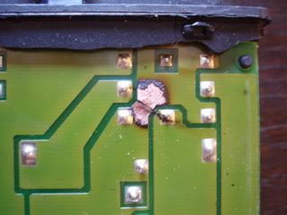
The car now will not start as there is no feed to the coil, injector etc. due to the burnt out track. I don't know why this circuit burnt out though, as all was running well before hand. I am at a loss now as to what to do, I have checked all my wiring and it appears to be correct. There are however 2 wires on the engine loom plug which I cannot find in the Haynes manual:
White/Brown
Brown/Yellow
Now i'm pressuming that as the above white/pink wasn't the white/red the Haynes said it should be that these are also a different colour in the book. I have tried to find them in the book diagrams but have turned up nothing. I have searched the forum and information points to the white/pink wire being related to the imobiliser. I found out that the car did have an imobliser on it, but i would have thought that if this was the fault, the car would not run at all?
I hope this all makes sense and any help grately appreciated
Gary