As some may know im having troubles with my gauges....
now before i buy a replacement 2 clock cluster and add on the tacho from my existing one id like to ask a couple of questions
is the voltage regulator built into the tacho? (sounds stupid if it is seing as not all minis had the tacho) because after mismantling the gauges all i found was the cogs etc for the speedo and the wire elements for the fuel/temp gauges
iv been told if the gauges are at fault theres nothing that can be done to fix em hence why im ready to buy a replacements
before i buy it..i just want to run through the checks iv already made..shorting the sensor ends causes both gauges to read as full/Hot.
out of the multiplug is there a wire to check the voltage of for the gauges incase the problem is external....but if the regulator is built into the clocks even though i cannot find it, i would have guesses it to be 12V on the multiplug end?
...what else could be at fault?


Temp/fuel Gauge On A Later Nippon S Gauge Set
Started by
stormintrooper
, Dec 28 2009 06:24 PM
31 replies to this topic
#2

Dan
-

- TMF+ Member
-

- 21,354 posts
On Sabbatical
Posted 28 December 2009 - 07:08 PM
It's inside the fuel / temp gauge. It's what looks like a long bi-metal spring with a heater at the bottom of the guage pod.
#3
stormintrooper
-
- Members
-
- 2,072 posts
Up Into Fourth
Posted 28 December 2009 - 07:49 PM
those are the regulators? i know those are what move the needles
#4
dklawson
-

- TMF+ Member
-
- 10,923 posts
Moved Into The Garage
- Name: Doug
- Location: Durham, NC - USA
- Local Club: none
Posted 29 December 2009 - 02:43 AM
Dan, do you remember who posted the pictures of the inside of the NS gauges? We really ought to find those pictures and archive them.
Stormintrooper, according to Taffy, some of the early NS gauge clusters still used an external voltage stabilizer. However, I've only seen pictures of the insides of what must be the later type which (as Dan said) have the stabilizer built into one of the gauges.
You are correct that the gauges work by the heating of a bimetallic element wound with resistance wire. However, in the pictures I mentioned above, on one of the gauges there was clearly a second bimetallic element wrapped with resistance wire... and terminated on one end by a set of contact points. Basically it was a open-frame version of the Smiths stabilizer.
On another recent thread I suggested something that I will likely never have the resources to try... but you might be able to.... Jupitus was selling the solid state stabilizer chips. I can envision a very careful dissection of the later NS gauge cluster and wiring in the solid state chip in place of the NS stabilizer. It shouldn't be too hard if you're comfortable taking the gauge cluster apart.
#5
stormintrooper
-
- Members
-
- 2,072 posts
Up Into Fourth
Posted 29 December 2009 - 06:31 PM
i have had the cluster completley stripped down many times 
hmm....i can't say for certain as i dnt remember fully but as memory serves i have only ever found two of the bimetallic elemtns..one for each needle..might this sugest i have a stabiliser located elsewhere?
if so where am i likely to find it?
hmm....i can't say for certain as i dnt remember fully but as memory serves i have only ever found two of the bimetallic elemtns..one for each needle..might this sugest i have a stabiliser located elsewhere?
if so where am i likely to find it?
#6
dklawson
-
- TMF+ Member
-
- 10,923 posts
Moved Into The Garage
- Name: Doug
- Location: Durham, NC - USA
- Local Club: none
Posted 29 December 2009 - 06:54 PM
Taffy1967 is your man. I'd send him a PM since he has either missed this thread or is not checking the board.
EDIT: I found what I mentioned above. Trooper, take a look at this old thread, specifically page 2.
http://www.theminifo...x...ippon&st=15
Scroll down to the SECOND set of pictures posted by garrett3. The top picture in his second set shows ONE of the NS gauges. In that picture you will notice that the gauge has TWO bimetallic fingers wrapped with resistance heating wire. The TOP finger/windings has a set of points on the "right" end. (Look below the brass nut with the red varnish on it). Those points open and close and are the equivalent of the Smiths stabilizer.
(Here's a direct link to garrett3's picture)
http://i54.photobuck...kstrip010-1.jpg
Garrett3 suggested or said that these gauges were from an SPI so your gauges may be different. Taffy should be able to tell you.
#7
stormintrooper
-
- Members
-
- 2,072 posts
Up Into Fourth
Posted 29 December 2009 - 07:22 PM
well i know its been some time but i know for sure my needle assembly did not look anything like that 
#8
stormintrooper
-
- Members
-
- 2,072 posts
Up Into Fourth
Posted 03 January 2010 - 06:37 PM
got some pictures now
thats my fuel gauge needle set up
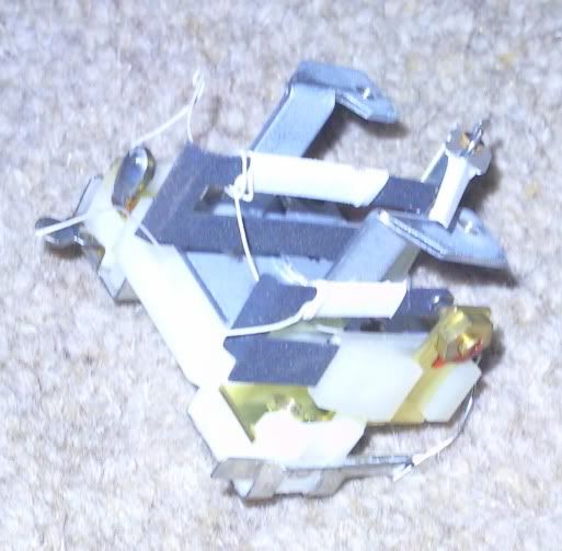
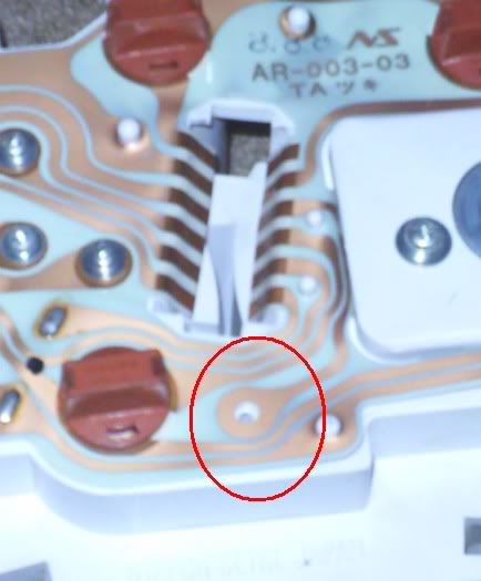
also found part of the printed circuit that makes no sense to me
thats my fuel gauge needle set up
also found part of the printed circuit that makes no sense to me
#10
Dan
-
- TMF+ Member
-
- 21,354 posts
On Sabbatical
Posted 03 January 2010 - 11:51 PM
Sorry Stormin but your gauge is essentially exactly the same as the one posted in the thread Doug linked (sorry I didn't reply Doug, I've been away for new years). I think the apparent difference comes from the fact that later clusters have both the minor gauges mounted to one frame where yours have them as seperate units. The second bi-metal spring on that unit is the voltage regulator, it has adjustable points. If you were to apply 12v to this gauge you would see the spring vibrating. The points are adjusted until the mean voltage produced is 10. The PCB has unused tracks, remember that when this gauge cluster was first designed by Smiths it wasn't used exclusively in the Mini and even in the Mini it wasn't only used in the UK. Other territories have laws requiring extra warning lamps and electronics.
#11
stormintrooper
-
- Members
-
- 2,072 posts
Up Into Fourth
Posted 03 January 2010 - 11:57 PM
ah right ok...well in that case i need to figure a way of applying a constant 12V.......any sugestions? and also what is done to adjust them if the voltage is too high/low?
is it to do with the little brass nut?
is it to do with the little brass nut?
Edited by stormintrooper, 04 January 2010 - 12:06 AM.
#12
stormintrooper
-
- Members
-
- 2,072 posts
Up Into Fourth
Posted 04 January 2010 - 12:05 AM
and ok yh just looked at the other picture and now i recognise it from another angle/upside down too
#13
Dan
-
- TMF+ Member
-
- 21,354 posts
On Sabbatical
Posted 04 January 2010 - 12:15 AM
Surely you can come up with a source of 12V, I assume you have a car bettery there somewhere since you have a car!  Actually you should be using 14 volts but a freshly charged battery will be good enough. Make a test rig (including a fuse) to connect 12v to the voltage stabiliser input and earth the gauge output (yes the needle will move). Then check the voltage at the junction between the stabiliser and gauge heater elements. It needs to be close to 10v. As you suggest, the adjustment is by using the locknut and the screw of the points. Check the points are dressed flat though, they work just the same as ignition points do and pitting will cause them to operate early. Be subtle, it doesn't take much adjustment and you don't want to ruin them. The varnish is just to lock the nut in place, you should find it will crack away easily enough and it can be replaced with nail varnish once you are finished. If you want to replace it with something solid state, cutting out that whole heater element and replacing it with an appropriate Zener or other chip will be quite simple. You will just need to add an earth.
Actually you should be using 14 volts but a freshly charged battery will be good enough. Make a test rig (including a fuse) to connect 12v to the voltage stabiliser input and earth the gauge output (yes the needle will move). Then check the voltage at the junction between the stabiliser and gauge heater elements. It needs to be close to 10v. As you suggest, the adjustment is by using the locknut and the screw of the points. Check the points are dressed flat though, they work just the same as ignition points do and pitting will cause them to operate early. Be subtle, it doesn't take much adjustment and you don't want to ruin them. The varnish is just to lock the nut in place, you should find it will crack away easily enough and it can be replaced with nail varnish once you are finished. If you want to replace it with something solid state, cutting out that whole heater element and replacing it with an appropriate Zener or other chip will be quite simple. You will just need to add an earth.
#14
stormintrooper
-
- Members
-
- 2,072 posts
Up Into Fourth
Posted 04 January 2010 - 12:36 AM
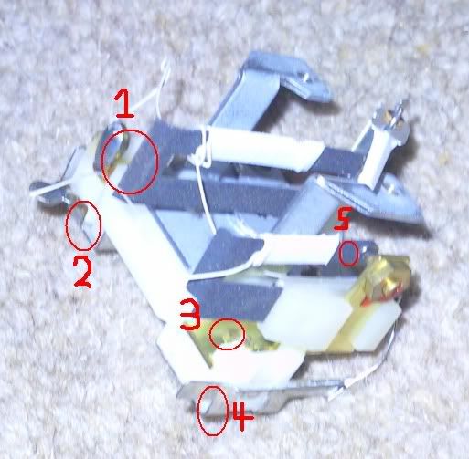
is number 2 the stabiliser input? and does it matter whether i use points 3 or 4 as a ground as both points are joined by wire as far as i could tell?
and is number 5 where i should test the voltage?
#15
Dan
-
- TMF+ Member
-
- 21,354 posts
On Sabbatical
Posted 04 January 2010 - 12:49 AM
From the photo, and only having one angle, I find it hard to tell. Can you take a photo with a clearer angle on the layout of the wires? You will need to earth the stabiliser and the gauge heater. I would say that 2 is probably the stabiliser heater input. The voltage should be checked at the input to the gauge heater. As I said though it's hard to tell without more of a clear idea of the layout.


1 user(s) are reading this topic
0 members, 1 guests, 0 anonymous users


