Stormintrooper, as Dan said, it's hard to tell what's connected where from the picture you posted. Can you try again with photos of both sides and if possible, can you play with the contrast a bit before saving the picture?
All I can say from the first picture is that the area marked #5 is the contact region of the stabilizer. Functionally it should behave and be wired similarly to what is shown in the schematic on page 2 of my stabilizer PDF
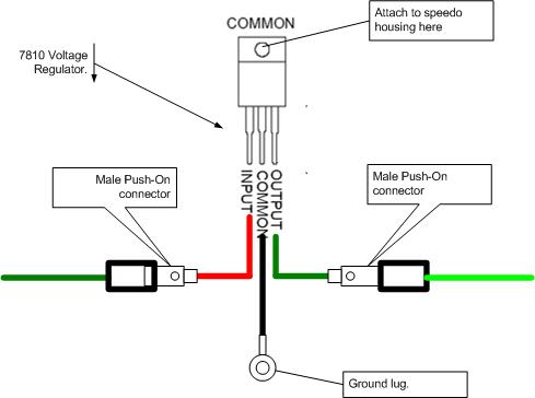
http://home.mindspri...eStabilizer.pdfThat is to say, the terminal connected directly to the brass adjusting nut (near 5) should be the "input" of the stabilizer. The resistance wire wrapped around the stabilizer bimetallic element should be connected to the bimetal part on one end. The other end of the resistance wire should have an earth connection. Finally, the bimetallic strip itself should be connected to a terminal. That connection will be the "output" supplying the two gauges.
Please do post more pictures if you can showing the gauge from as many angles as necessary to illustrate each connection.


 ) id personaly say 3 was the earth to the stabiliser as it touches the stabiliser metal strip when the 2 are connected and 4 being the one for the needle
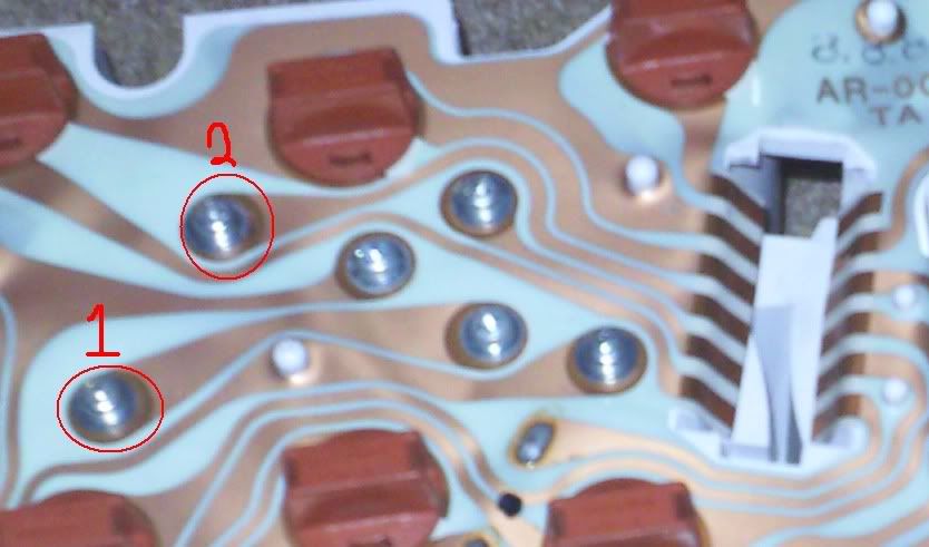


