Jump to content


Photo
- - - - -

1982 Austin Mini - Project Who?


  • Please log in to reply
848 replies to this topic

#616 JonnyAlpha

JonnyAlpha

    Up Into Fourth

  • Members
  • PipPipPipPipPipPipPipPipPip
  • 2,744 posts
  • Location: North Devon
  • Local Club: Exmoor Minis

Posted 18 December 2016 - 09:34 PM

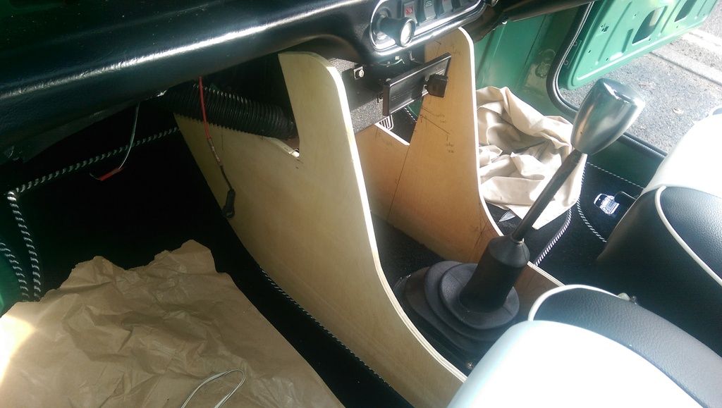
Well no updates for a while but I have been tinkering - still lots of cosmetics to do and I have been concentrating on getting some tunes in the car.


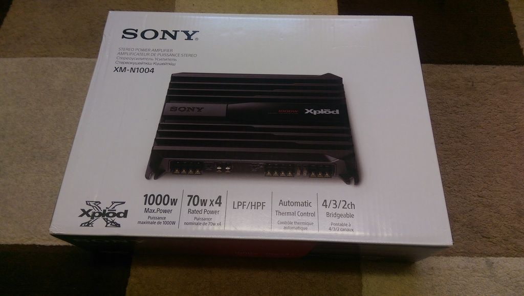
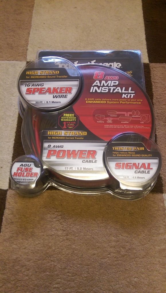
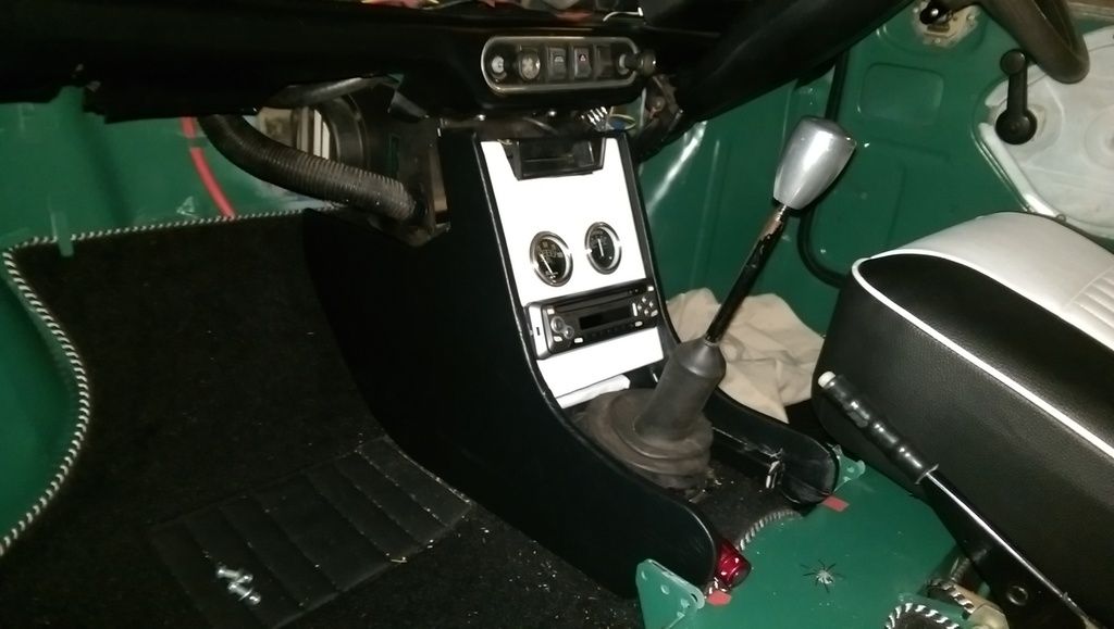
When we picked the car up it had a Pioneer Stereo fitted. My aim is to install a Raspberry Pi Computer as an In Car Entertainment System with a 7 Inch Touchscreen. I had already bought most of the hardware so I decided to try and get this temporarily installed and working. For the audio out I would have to hack into the Pioneer (which I did) but decided to fit a separate Amplifier which I have just received (Christmas Present).


Rather than add the whole 'what I did on here' I will link it to a separate blog that I am running for it. The blog is here. I will post on here the odd pic though. 


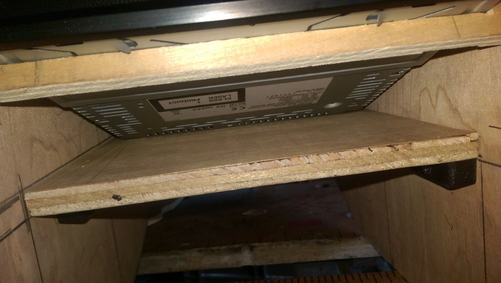
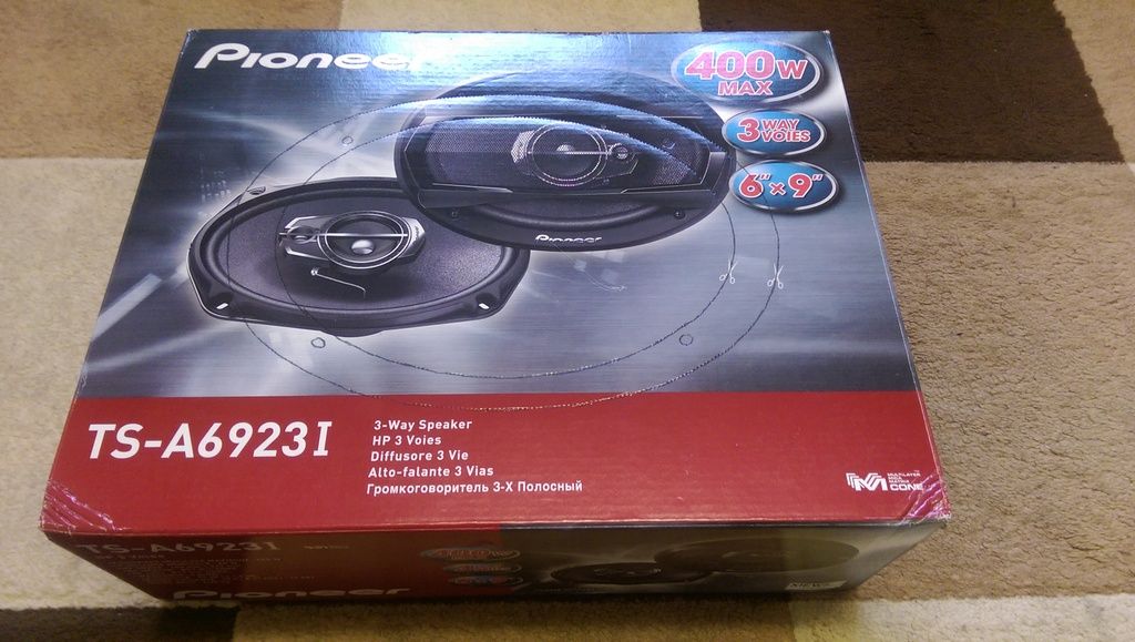
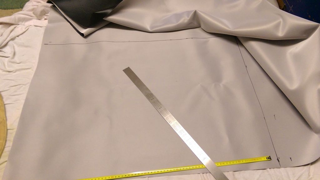
The speakers are rather large (6 x 9 Coaxial) so after contemplating where to put them I have opted to fit them under the rear seats. To do this I would need a speaker board. As I was also going to build a custom dash and centre console I went of and bought some Plywood. For the cost of the plywood I should have bought a ready made speaker board as they are only £40!!


Anyway being a gluten for punishment I opted to do this myself.


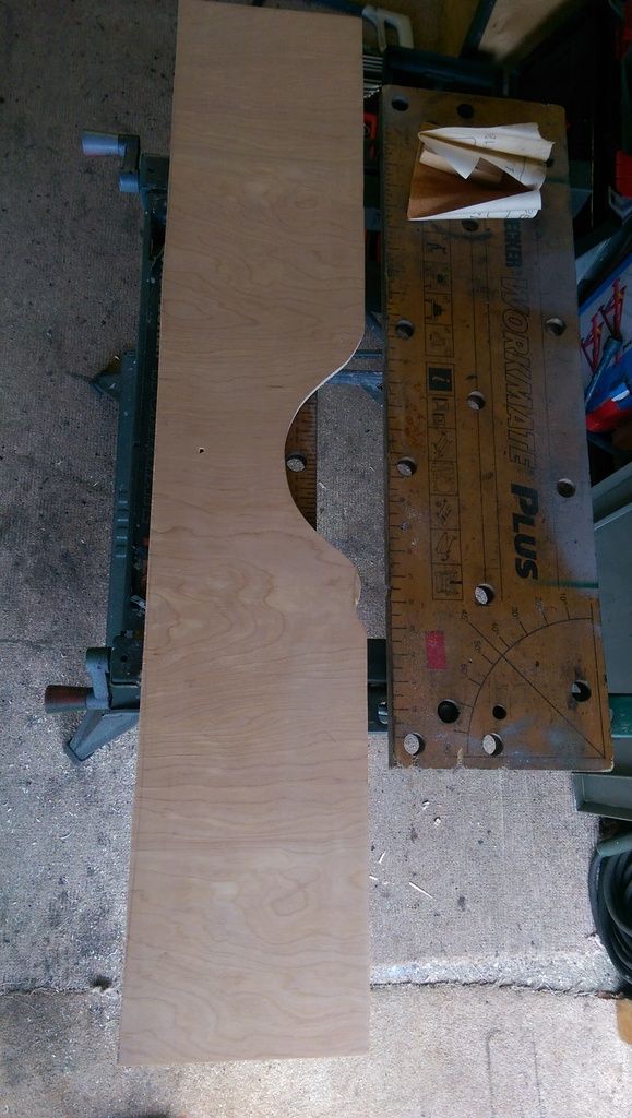
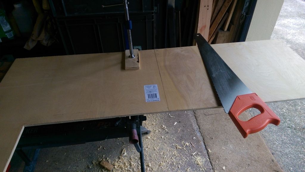
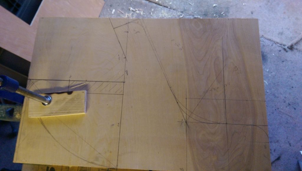
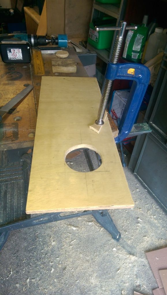
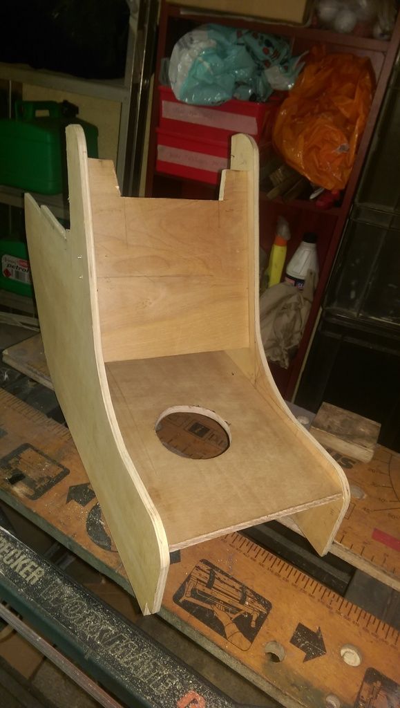
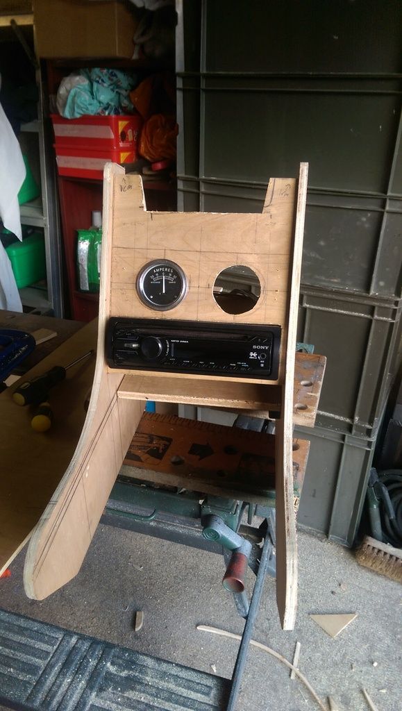
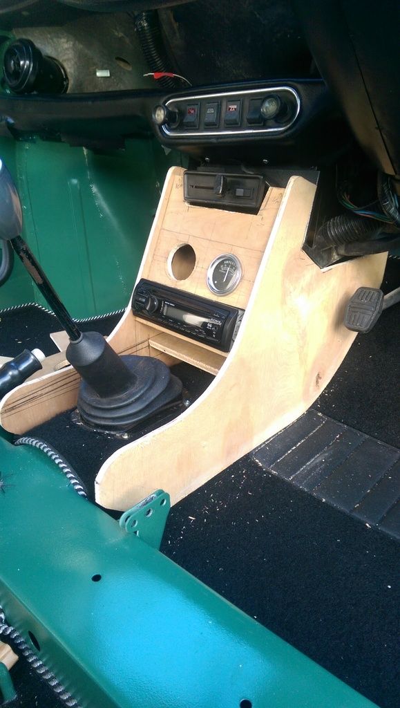
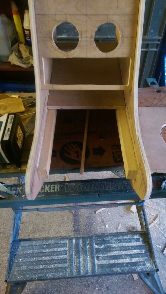
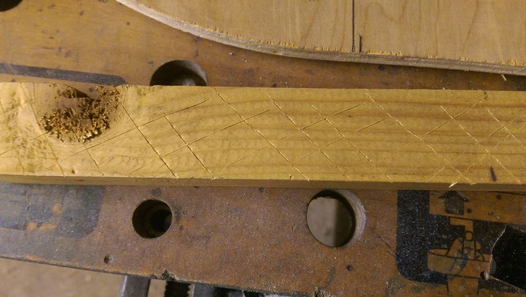
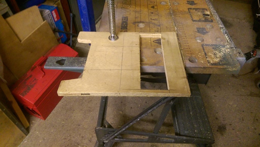
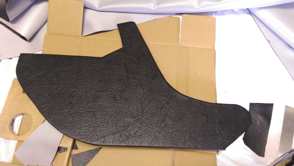
Here's the main piece for the speaker board cut out with the first mark for the tunnel:


IMAG7326_zps97ewbpmx.jpg


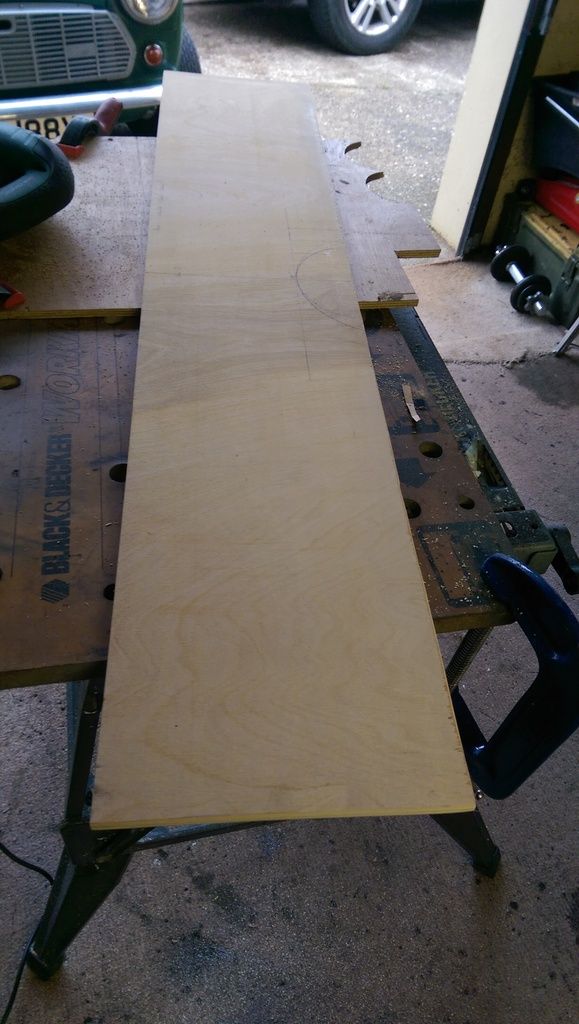
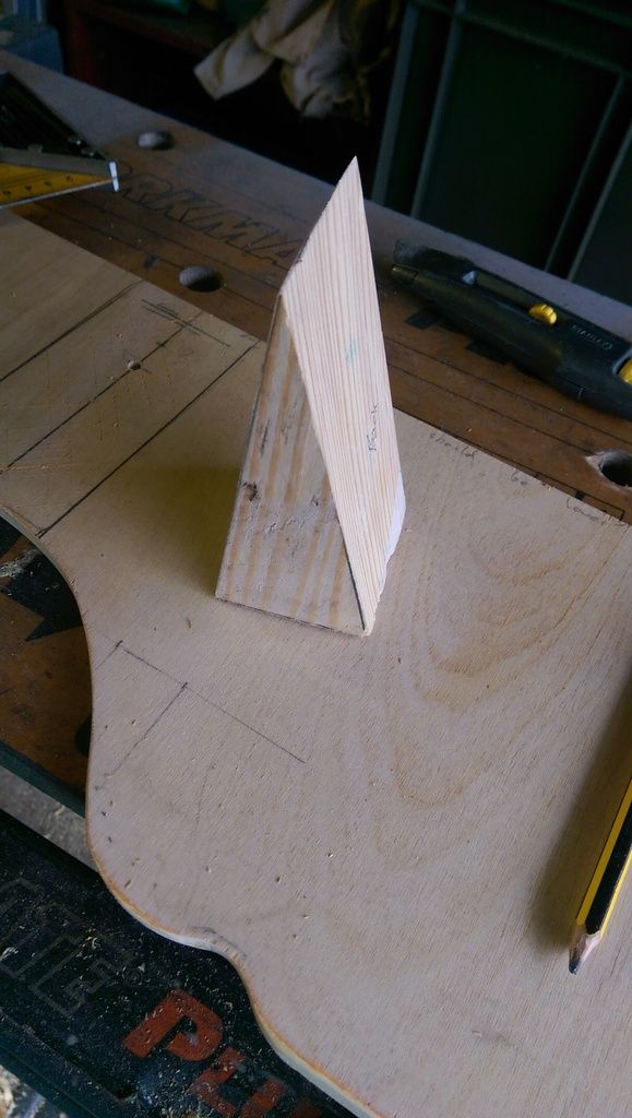
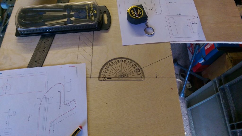
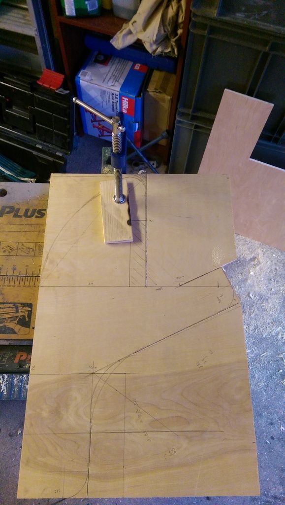
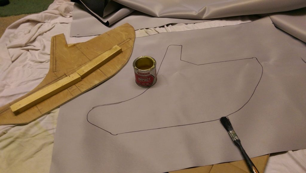
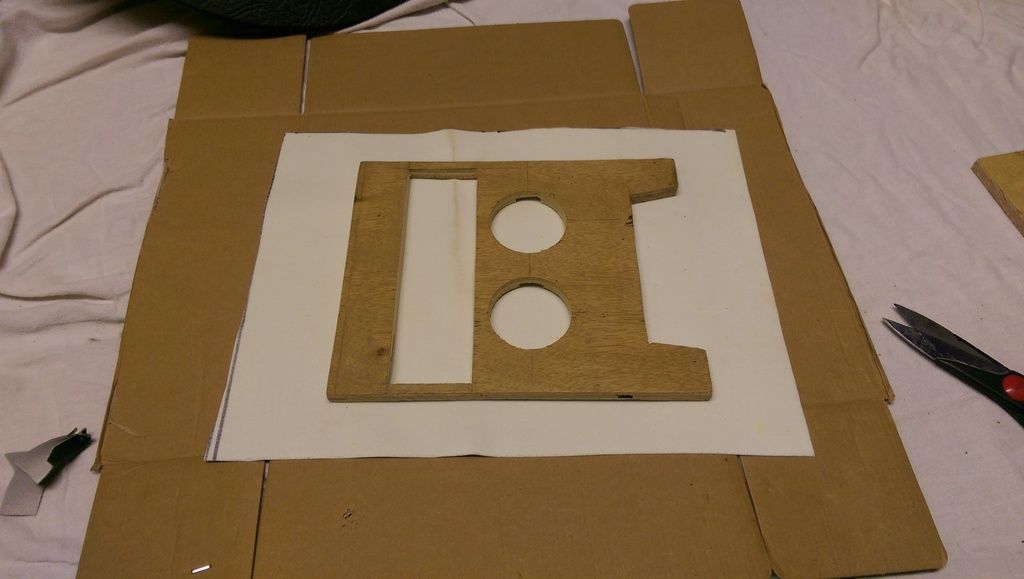
The template that I downloaded didn't seem right as far as overall length and tunnel shape so I had to do some adjustments and used a separate piece of wood and a couple of small round containers to get the first stab done:


IMAG7325_zpshhdnmfrh.jpg


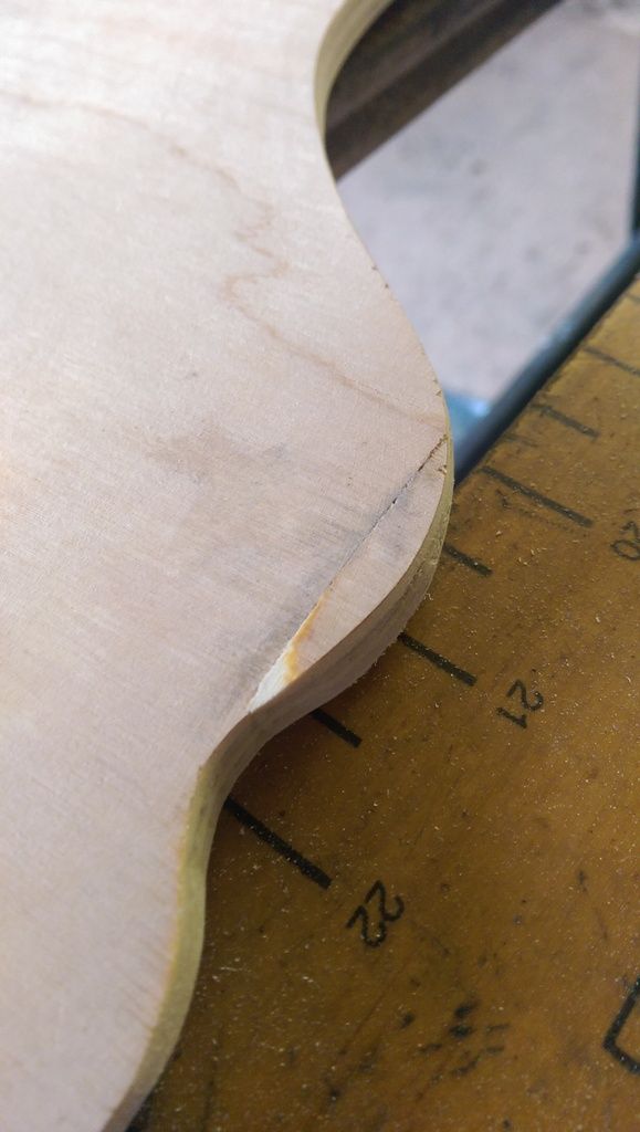
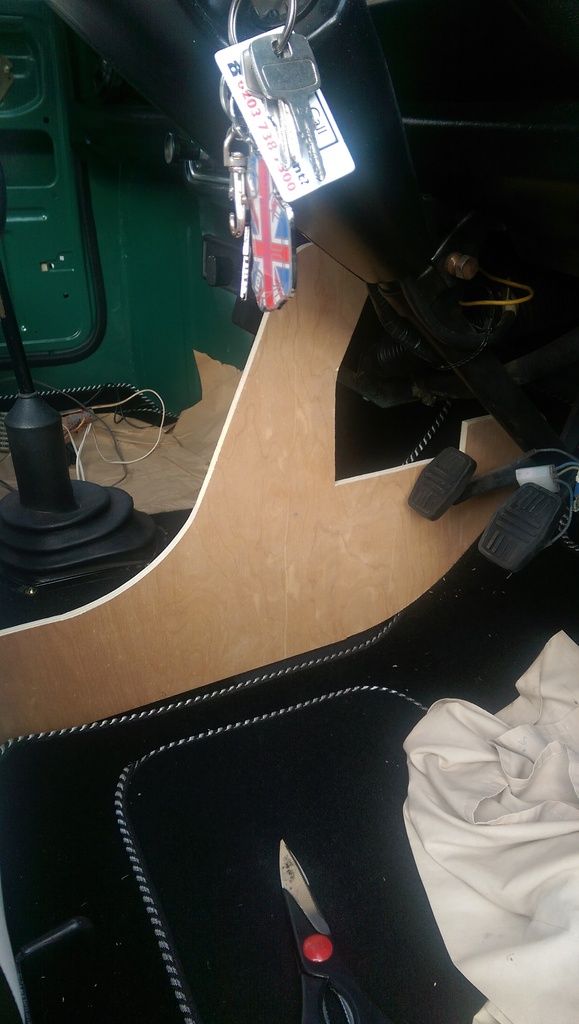
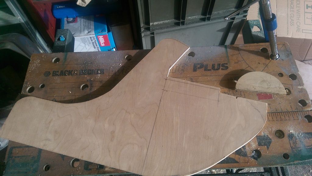
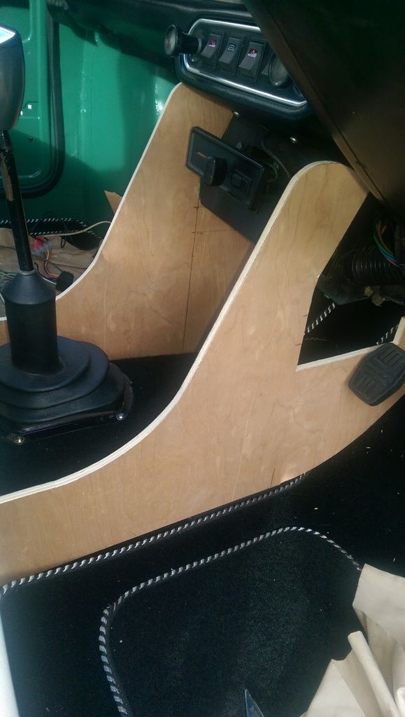
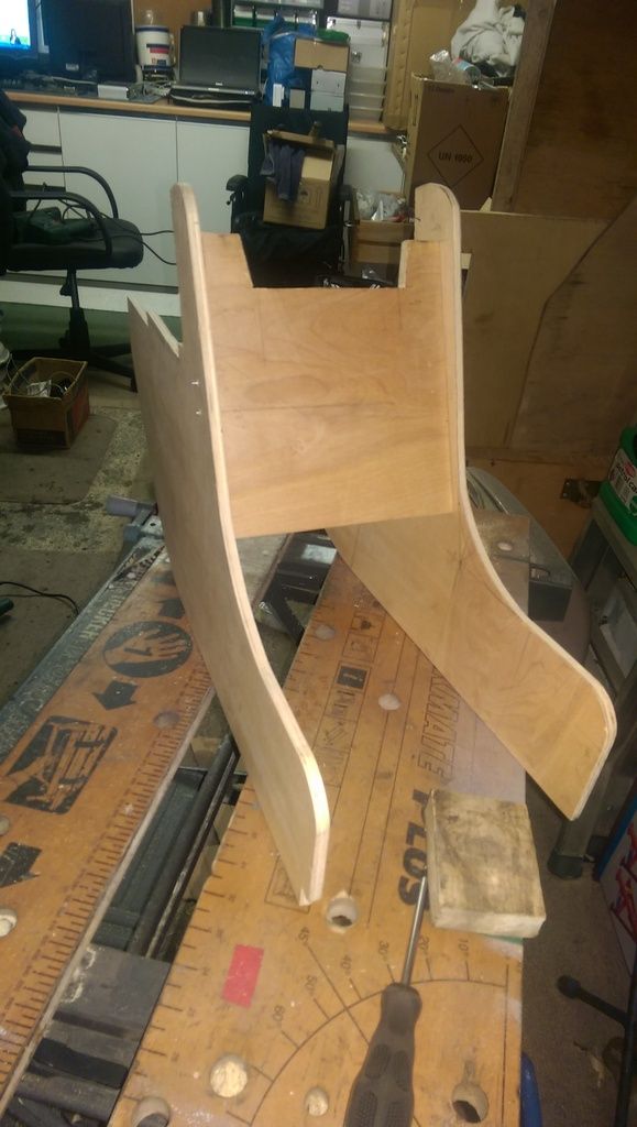
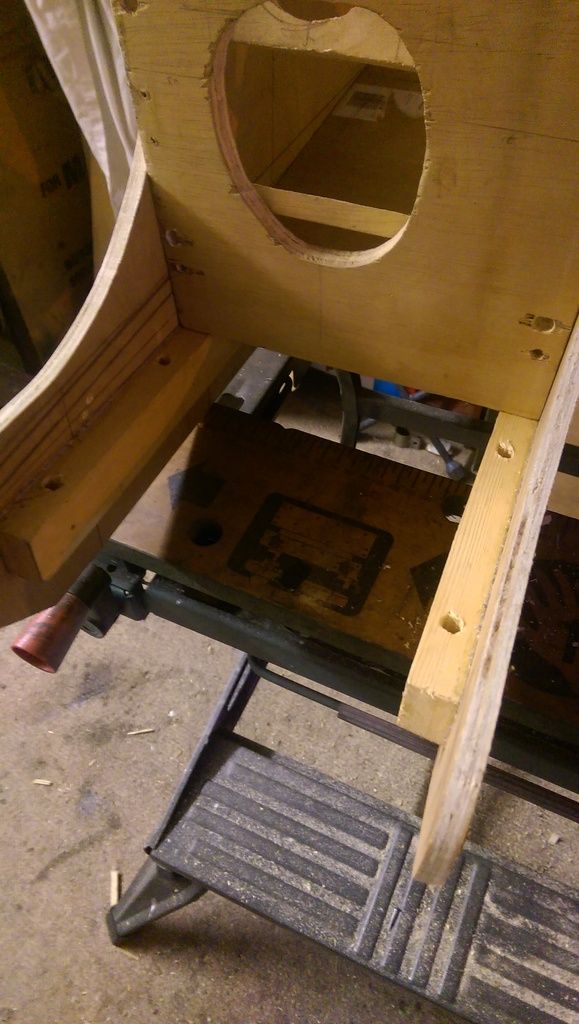
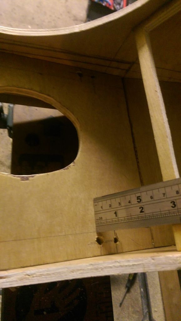
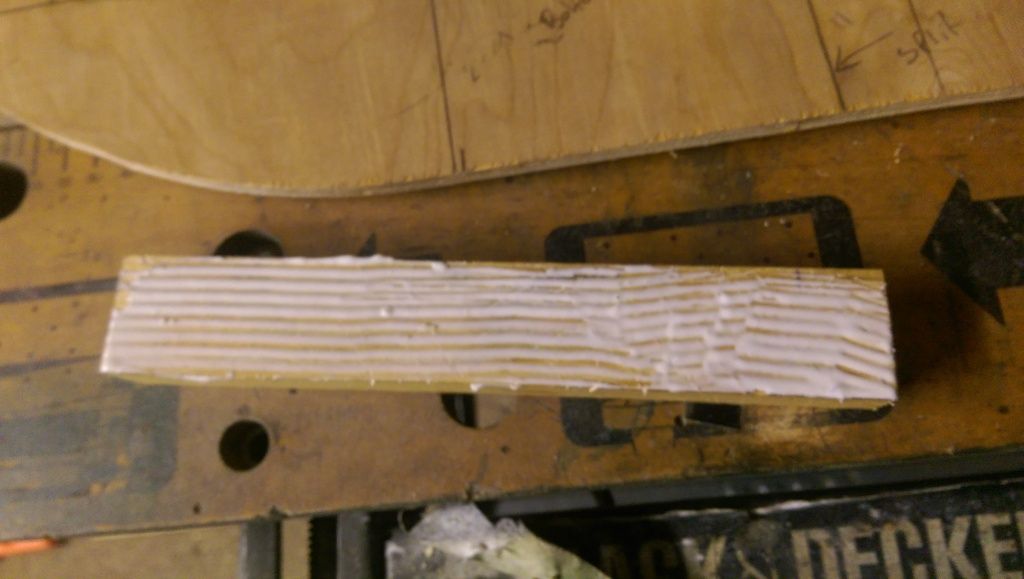
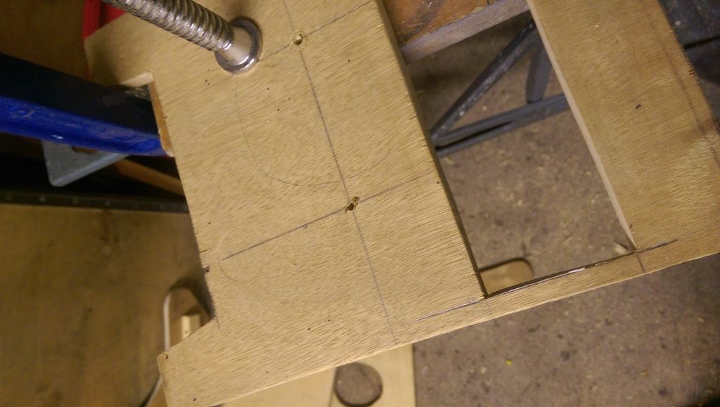
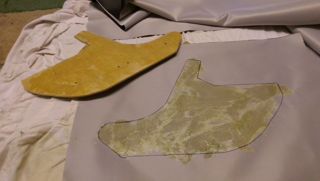
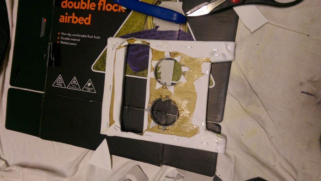
I then did several test fits marking with a pencil and making several trimmings before I got the profile that I wanted.

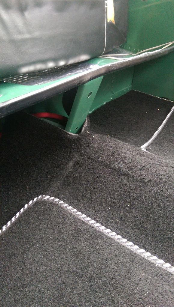
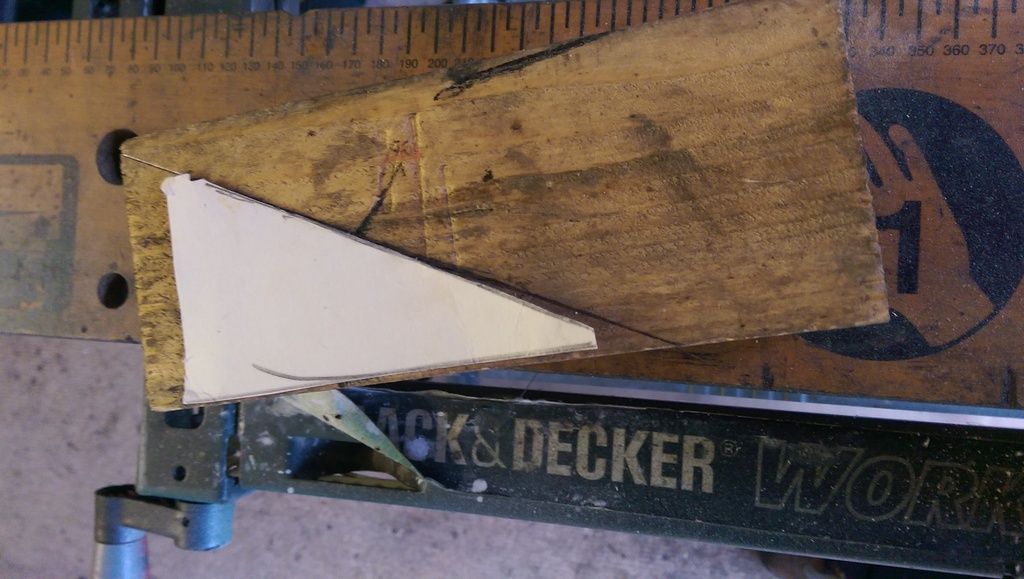
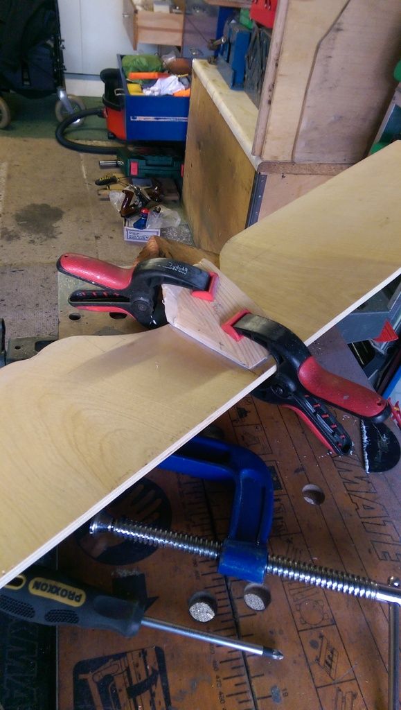
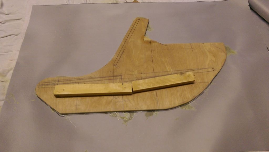
I decided that the top front of the board will sit flush with the edge of the rear seat base as I may put a couple of screws at either end to hold it in place. The main support / fixing will be through the hole in the upright strut under the centre of the rear seat. To keep the speaker board vertical I'll fashion a wedge that will be fixed to the rear of the speaker board. The board will probably be held in place with piece of threaded bar fixed to the upright strut and held on with a wing nut that can be undone from the front?


OMG - I just had a search on Google for some ideas on how to fix the speaker board and found this site. They sell ready made boards for £15 plus delivery!!!!  


#617 James_eaton_thewholething

James_eaton_thewholething

    One Carb Or Two?

  • Members
  • PipPipPipPipPipPipPip
  • 1,063 posts
  • Location: Manchester

Posted 19 December 2016 - 08:11 PM

Looking really good mate. Wish I could crack on with mine and get it finished

#618 JonnyAlpha

JonnyAlpha

    Up Into Fourth

  • Members
  • PipPipPipPipPipPipPipPipPip
  • 2,744 posts
  • Location: North Devon
  • Local Club: Exmoor Minis

Posted 19 December 2016 - 08:25 PM

Looking really good mate. Wish I could crack on with mine and get it finished


Thanks James - it took forever but you'll reap the benefits later :-)


#619 James_eaton_thewholething

James_eaton_thewholething

    One Carb Or Two?

  • Members
  • PipPipPipPipPipPipPip
  • 1,063 posts
  • Location: Manchester

Posted 19 December 2016 - 08:33 PM

Hopefully, I'm in the middle of installing the rear beam and arms. Had to make the holes bigger on the beam to get it to fit been a right pain.

#620 JonnyAlpha

JonnyAlpha

    Up Into Fourth

  • Members
  • PipPipPipPipPipPipPipPipPip
  • 2,744 posts
  • Location: North Devon
  • Local Club: Exmoor Minis

Posted 19 December 2016 - 08:48 PM

Hopefully, I'm in the middle of installing the rear beam and arms. Had to make the holes bigger on the beam to get it to fit been a right pain.


I read your build the other day - what's the rear beam for? is it part of a custom Subframe?


Coxie on this Forum popped around and helped with my Subby - I had planned to do it alone, we spent a good couple of hours on it!!! Got there in the end.


#621 James_eaton_thewholething

James_eaton_thewholething

    One Carb Or Two?

  • Members
  • PipPipPipPipPipPipPip
  • 1,063 posts
  • Location: Manchester

Posted 19 December 2016 - 09:51 PM

The rear beam is instead of using a subframe, mainly because I'm using coilovers also saves a little weight. A lot of people don't like them but this isn't going to be a car that is standard and is going to be a toy. Plus my rear subframe was toast and would only buy a new one if I was going to use it. This option was cheaper too

#622 JonnyAlpha

JonnyAlpha

    Up Into Fourth

  • Members
  • PipPipPipPipPipPipPipPipPip
  • 2,744 posts
  • Location: North Devon
  • Local Club: Exmoor Minis

Posted 20 December 2016 - 07:11 PM

Finished shaping the Speaker Board, had to add a small recess for my battery cable which runs under the carpet:


IMAG7341_zps5i9ulohi.jpg


Had to do a small repair (I love wood):


IMAG7344_zps1fgw1ifa.jpg


Next I started to fabricate a wedge that will sit behind the Speaker Board and butt up against the centre strut which will keep the board upright:


IMAG7347_zpsy3ntpnbm.jpg


I made a cardboard template to get the angle for the wedge:


IMAG7346_zpsfxtsscaa.jpg


And cut it out of an old piece of wood. After several test fits and trimming (a lot of trimming) it was the correct size and shape:


IMAG7350_zpscncqgvq9.jpg


I marked the Speaker Board to show where the wedge would fit and keyed up the mating surfaces. I then applied some PVA and screwed / clamped the wedge in place to leave overnight.


IMAG7351_zpszhvlzyd7.jpg


Next I decided to make a start on the Centre Console. The two sets of plans I had needed some deciphering.

First from the same piece of plywood used for the Speaker Board I cut two pieces 601mm long:


IMAG7354_zpsehjz2ui9.jpg


To mark the angles and curves I had to hunt around my house for a Protractor and Compass. The radius of the curves is not marked so it was pretty much a guess to get the correct curvature:


IMAG7355_zpsj4b0wgpd.jpg


Here's one side marked out:


IMAG7356_zps31soufem.jpg


I cut out the straight edges with my 20 Inch Cross Cut Saw:


IMAG7359_zps00aktjde.jpg


Then finished the rest of with my recently repaired JigSaw:


IMAG7360_zpsjpgwonxj.jpg


Had a quick test fit and I am not sure how it is supposed to fit? From looking at picks on the net the rear of the console slips either side of the Heater Matrix?

Until I cut out all four pieces and fit them together I'll not know?


Edited by JonnyAlpha, 20 December 2016 - 07:29 PM.


#623 JonnyAlpha

JonnyAlpha

    Up Into Fourth

  • Members
  • PipPipPipPipPipPipPipPipPip
  • 2,744 posts
  • Location: North Devon
  • Local Club: Exmoor Minis

Posted 22 December 2016 - 08:53 PM

Back at it today - bloomin cold this morning in the garage.


Cheked my Speaker Board only to realise I had glued the wedge on the wrong side. Not to worry just means I need to cut a small recess for the Power cable under the carpet :-(


Played around and trimmed up the R/H side of the centre console:


IMAG7364_zpsuaawiaz5.jpg


Looks like I measured the cut out for the Heater Matrix wrong as its too low. I may cut most of this side off though to get at the clutch?


Started on the other side using most of the R/h one as a template (apart from the Heater cut out of course):


IMAG7366_zpsct5h1ezk.jpg


After some trimming of the upper section and the rear for the heater hoses, here they both are:


IMAG7367_zpsvkbmwjjk.jpg


IMAG7368_zpsvtg2stna.jpg


Next I made the lower centre piece:


IMAG7369_zps68f4gjjp.jpg


Then I made and fettled the upper centre section and with one side in place I tried to see where it should connect and screwed the two pieces together. Next I fitted the R/H side also (more guess work than measuring?


IMAG7370_zpsput3eyou.jpg


I did try and fit the console in the car to see where the base would fit but without taking the seats out it ain't going in!!!

So I had a look at some photos and fitted it using some work top securing brackets.


IMAG7372_zpsmra2tkve.jpg


On all the pics I have seen on the web no one is using the standard Gear Change Gaiter? With the console base only dry fitted in place it looks as though some of the gaiter will pull up through the hole in the console but I will have to see when I get the seats out.


Problem is I need to do this outside and the weather is looking crabby for the next few days - oh and I need to do some Christmas Shopping  :ohno:


#624 JonnyAlpha

JonnyAlpha

    Up Into Fourth

  • Members
  • PipPipPipPipPipPipPipPipPip
  • 2,744 posts
  • Location: North Devon
  • Local Club: Exmoor Minis

Posted 22 December 2016 - 09:02 PM

Also some gauges turned up today:


IMAG7376_zpso8vslztj.jpg


I got them from a local Facebook sales group. The one that's missing is a temperature gauge:


IMAG7377_zpssqforgyc.jpg


The box that they came in has all the fittings / pipes etc:


IMAG7378_zpsuraeyeg5.jpg


I may only use the vacuum performance gauge and the amp metre. I already have a temp reading on the main instruments. Not sure about the Oil Pressure as its not electric?

The two gauges will fit nicely in my centre console under the radio?


Edited by JonnyAlpha, 22 December 2016 - 09:03 PM.


#625 Coxie

Coxie

    Speeding Along Now

  • Members
  • PipPipPipPipPip
  • 461 posts
  • Location: North devon

Posted 23 December 2016 - 06:33 AM

If you get one of these t pieces that screws into the block, you can run an oil pressure gauge and still have the warning light as it was
.http://www.minispare...Classic/TP.aspx

Edited by Coxie, 23 December 2016 - 06:34 AM.


#626 JonnyAlpha

JonnyAlpha

    Up Into Fourth

  • Members
  • PipPipPipPipPipPipPipPipPip
  • 2,744 posts
  • Location: North Devon
  • Local Club: Exmoor Minis

Posted 23 December 2016 - 09:46 AM

If you get one of these t pieces that screws into the block, you can run an oil pressure gauge and still have the warning light as it was
.http://www.minispare...Classic/TP.aspx


Ah hah - cheers mucker :-) You can't have enough gauges I guess - Rev Counter is on its way, it was on eBay sold as 'new' condition unknown - picked it up for about £8? 


Edited by JonnyAlpha, 23 December 2016 - 03:11 PM.


#627 JonnyAlpha

JonnyAlpha

    Up Into Fourth

  • Members
  • PipPipPipPipPipPipPipPipPip
  • 2,744 posts
  • Location: North Devon
  • Local Club: Exmoor Minis

Posted 27 December 2016 - 10:09 AM

More work yesterday trying to get the centre console finished so that I can install the radio. It's been really difficult getting it to fit exactly how I want it and also made a few mistakes on the way but I am getting there.


Trying to get the console into the car assembled proved impossible and in doing so I cut lots of bits off. Then I realise that the base centre section needs to be made as two separate parts that way the console can be slid in a lot easier and the piece that fits over the gear stick can slot in afterwards. All I need to do was work out the best way of securing this last piece without any fixings showing (solution later).


As I would be fitting a 7 Inch Touchscreen into the dash and as I also wanted install a glove compartment I would need to install the radio elsewhere - either under the dash or better still in the centre console. Before marking the location for the radio I had to find the spot that would ensure the radio was under the heater matrix enclosure. Doing this left a gap at the top with enough room to fit a couple of gauges. 


Here's the test fit of the radio and one of the gauges:


IMAG7391_zpswqtohtn3.jpg


After marking the cut outs for the radio I also noticed that the lower cross section under the radio was too narrow for stapling on vinyl and would also be a weak spot prone to snapping. When I test fitted the radio I also found that the radio hit the bottom section before being fully inserted. The solution would be to lower the bottom section as long as there was room.


Here's a pic showing the radio bottoming out on the centre piece of the console:


IMAG7393_zpspzm6s8mk.jpg


Test fit in the car to double check that the gauges have enough room:


IMAG7395_zpsu6bkzywv.jpg


The 9mm plywood is a little too thick for the securing brackets on the gauges so I will have to work that out before covering.


In order to affix the gear stick section I fitted a couple of support pieces. These were PVA glued and screwed in place :


IMAG7396_zpso37d4laf.jpg


I then marked the location for 4 x holes in the gear stick section of plywood and drill through these and the lower support pieces with an 8mm drill. The plan is to insert some dowel in the gear stick section to hold it in place:


IMAG7397_zps4wzmvjec.jpg


As mentioned above the cross piece under the radio is too narrow so the front facia needs to be recut and extended. The intention was to extend it so that it met the lower section of the console. When checking this on the console I realised that once in place the gear piece / dowling idea would not work as there would not be enough room to slot the piece in place - back to the drawing board. Solution is to shorten the gear stick section so that the join meets the facia or make the facia slightly short. If I decided to make it short I may make a small recess with a backing piece otherwise I can see objects sliding forward with insufficient room to get your hand in to retrieve them!!


IMAG7400_zps8aisdhiz.jpg


Meanwhile look what Father Christmas delivered:


IMAG7402_zpsa1ljhhxn.jpg


IMAG7403_zpslarlidqt.jpg


IMAG7401_zpsf0xp7wuv.jpg


I chose the Amp and Speakers a while back and purchased them from Car Audi Direct (recommended on here). I then spent ages researching fitting and wiring requirements before settling on a high quality installation kit (Rockford Fosgate 100% Oxygen Free Copper) which I got from Car Audio Security. I wasn't happy with the usual Vibe Slick and the slightly better KnuzConceptz kits does not have 100% Oxygen Free Wire. Although the length of cable run on a Mini probably means that the voltage loss in using Aluminium Clad Wire compared to 100% OFC is immaterial I decided on getting the better complete kit anyway. 


I was advised to get 4Gauge Wire however looking at all the guides and seeking advice online from Crutchfield (a USA site) 8Gauge is more than ample even if I later want to add a second Amp.


Can't wait to get it all rigged up.


P.S. I am in no way a 'Boy Racer' (no disrespect to anyone intended) and have no intention on going around blasting noise everywhere - I just wanted a good quality setup with minimal cost.  


Edited by JonnyAlpha, 29 October 2018 - 07:32 PM.


#628 JonnyAlpha

JonnyAlpha

    Up Into Fourth

  • Members
  • PipPipPipPipPipPipPipPipPip
  • 2,744 posts
  • Location: North Devon
  • Local Club: Exmoor Minis

Posted 27 December 2016 - 07:50 PM

Well apart from the last minute tinkering late tonight I finished the centre console. It turned out OK but to be honest I don't think I'll be starting up a vinyl recovering business as although it looks fine from the front the rear is a right mash of glue and staples!!!


I decided to use battens along the bottom to support the base. I cut them to length and keyed them with a stanley knife before clamping, glueing and screwing them in place:


IMAG7408_zpsd0js3ovq.jpg


IMAG7409_zps8u30qicw.jpg


Then I started making the new facia:


IMAG7410_zpsyl7pifw7.jpg


Then I marked out where I wanted the gauges and drilled a pilot hole:


IMAG7411_zpstlt59xyc.jpg


Then I used a 57mm hole saw which although seemed a little large, I thought that once the vinyl was on the gauges would be tight:


IMAG7413_zpsj9go6i0w.jpg


IMAG7412_zpsuynxcylp.jpg


And once everything was ready I started the covering process. First after working out how much I needed I marked and cut out the vinyl: 


IMAG7414_zpsx2rq8jy4.jpg


Then I drew around the side piece to be covered:


IMAG7415_zpsxj4p6jec.jpg


And spread on some Evo Stick Impact Adhesive:


IMAG7416_zps3xvvvsod.jpg


Then after spreading glue on the side piece as well after a couple of minute I attached them together:


IMAG7417_zpsnpj6im1u.jpg


I then set about stretching and stapling the covering. I made a few mistakes but managed to cover the piece to a reasonable standard:


IMAG7418_zpsxawebtz4.jpg


I wont show you a picture of the reverse side as its a bit of a mess (but won't be visible),


Next I started to cover the inner pieces using the same process. I decided to do these in white to match the rest of the interior:


IMAG7419_zpst91xnvly.jpg


Here's the back of the facia: 


IMAG7420_zpsmyrnjoab.jpg


Once everything was covered I set about putting it together. No pics I am afraid suffice to say the bottom rear piece was screwed in from the top and the facia was fitted using angle brackets.


Here it is in the car with the gauges and radio (not the one I am fitting) loosely fitted in place. Looks OK:


IMAG7425_zpsl1bkpdvq.jpg


Could do with painting the gear stick and gaiter :-)


#629 panky

panky

    Camshaft & Stage Two Head

  • Members
  • PipPipPipPipPipPipPipPip
  • 1,778 posts
  • Location: Cheshire

Posted 27 December 2016 - 07:53 PM

Looks ace :D


#630 JonnyAlpha

JonnyAlpha

    Up Into Fourth

  • Members
  • PipPipPipPipPipPipPipPipPip
  • 2,744 posts
  • Location: North Devon
  • Local Club: Exmoor Minis

Posted 28 December 2016 - 07:02 PM

Looks ace :D


Many thanks 


0 user(s) are reading this topic

0 members, 0 guests, 0 anonymous users