That's looking really good, well done that man

Thanks panky

Up Into Fourth

Posted 18 February 2017 - 07:38 PM
That's looking really good, well done that man
Thanks panky
Up Into Fourth
Posted 19 February 2017 - 03:40 PM
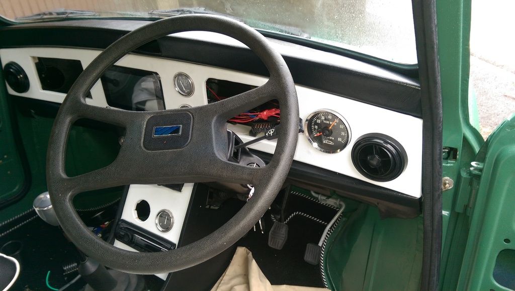
Now that I have some staples I secured some of the vinyl edges and then went about fitting and working out how to wire up the gauges etc.
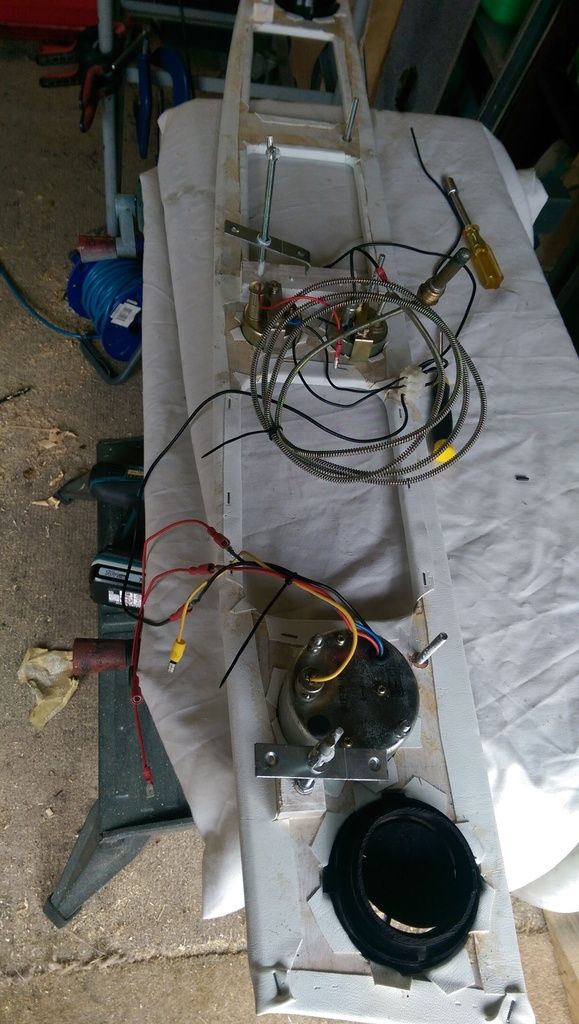
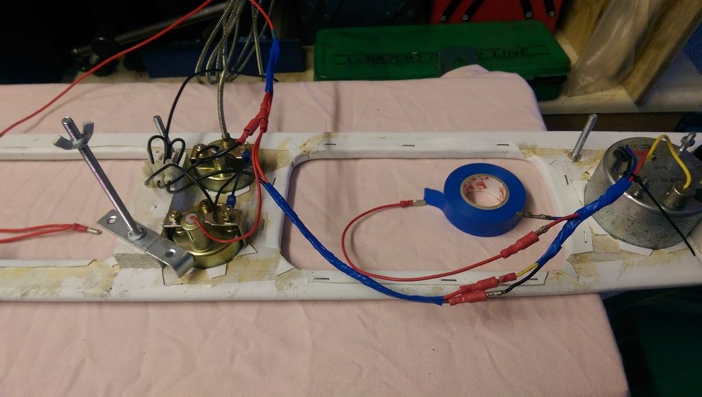
I fitted some extensions to the Rev counter and then stripped and fitted bullet connectors to the lighting cables coming out of the two smaller gauges.
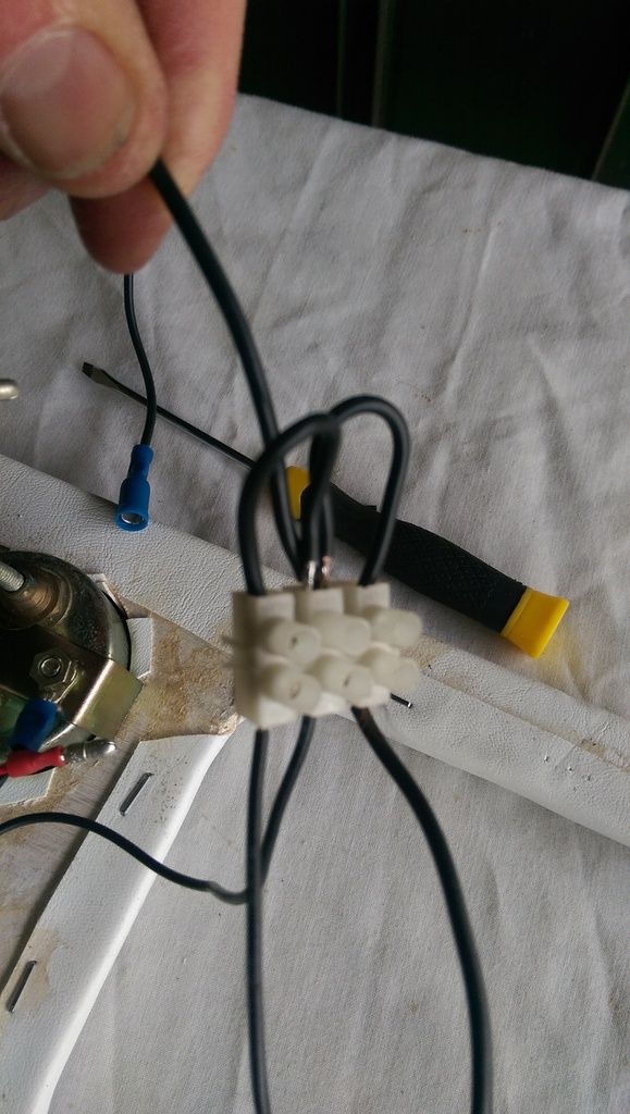
I believe they all need grounding so I made up some ground cables and found a suitable ground point. I ran a single cable from the ground point into the centre of a three way distribution point and then ran wires from the centre to the outer two. The three gauges (Rev Counter and two smaller gauges) were then connected to the other side of the distribution block.
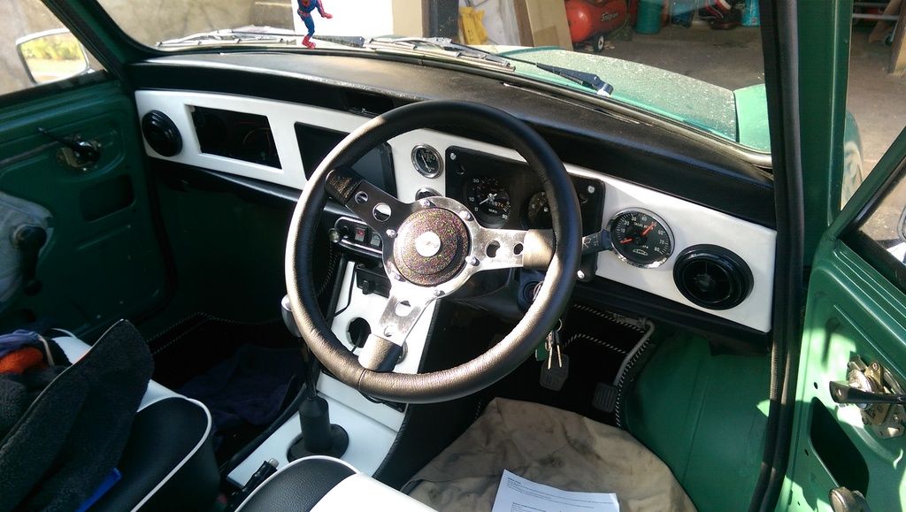
Being a little impatient I did a trial fit of the dash - mainly to see if the Rev counter worked.
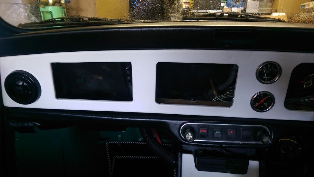
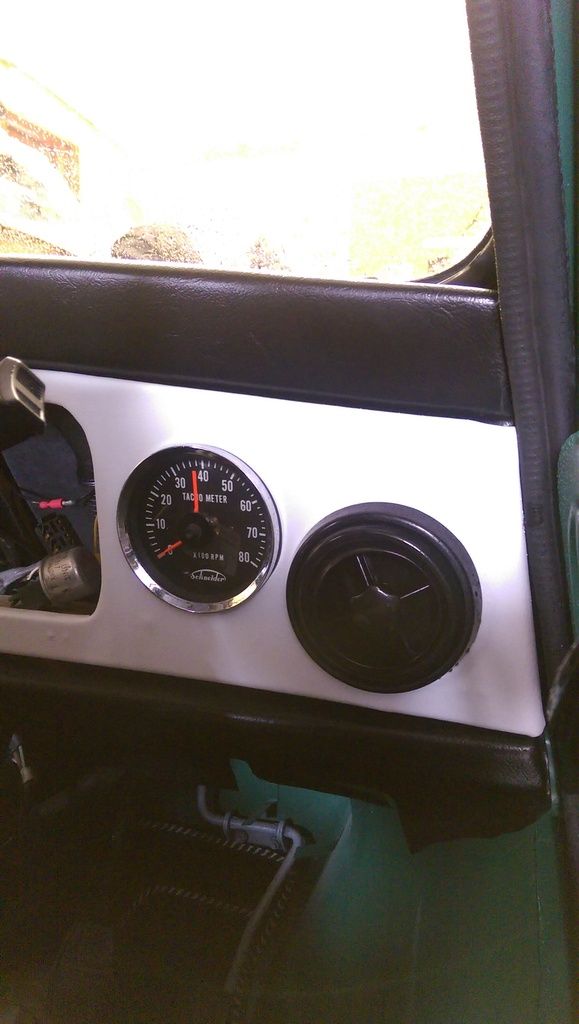
I will have to take the dash out again to finish it off and tidy the cabling but it's all coming together and looks good. I will have to wait to wire up some of the gauges, such as the Oil Temp, as I can't afford the adaptor yet.
Camshaft & Stage Two Head

Posted 19 February 2017 - 05:57 PM
I ran a single cable from the ground point into the centre of a three way distribution point and then ran wires from the centre to the outer two. The three gauges (Rev Counter and two smaller gauges) were then connected to the other side of the distribution block.
Try and avoid using choc-blocks if you can, they are a really bad solution in high vibration environments like cars. It would have been a better option to just find a good place to ground all of the wires individually.
Up Into Fourth
Posted 24 February 2017 - 08:16 PM
So after scouring the town for wire suppliers that didn't want to rip me off I got some 17Amp wire to run a new constant 12v feed to power the Radio / Car PC switch etc.
Trimmed it folded the end and tinned it with solder:
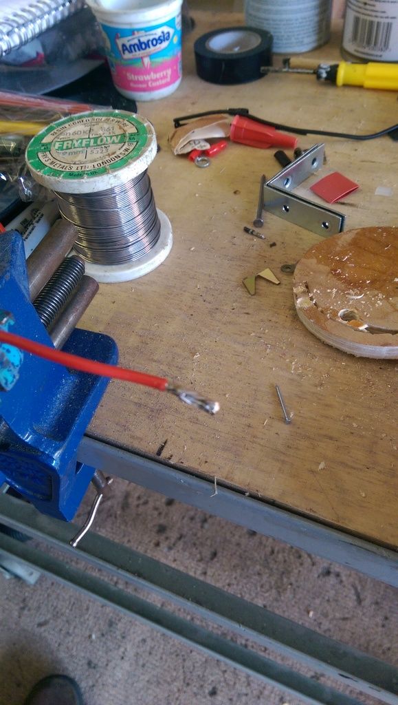
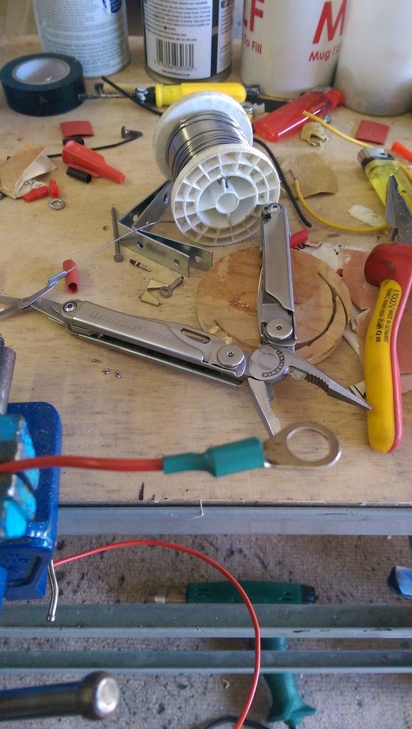
Then soldered it to a spare lug that I had left over from the amp install. Also fitted some heat shrink, sorry didn't have any matching red that would fit:
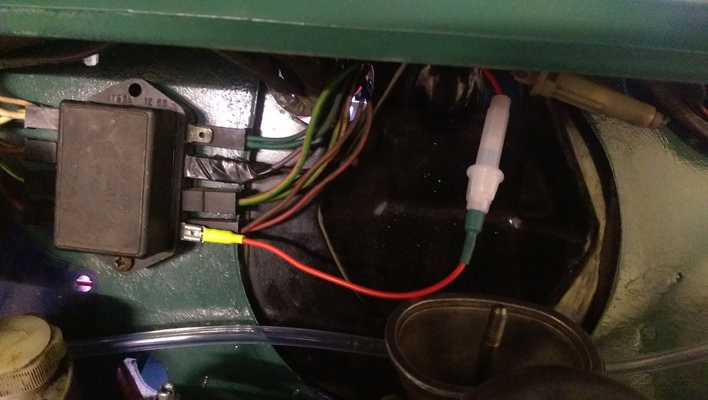
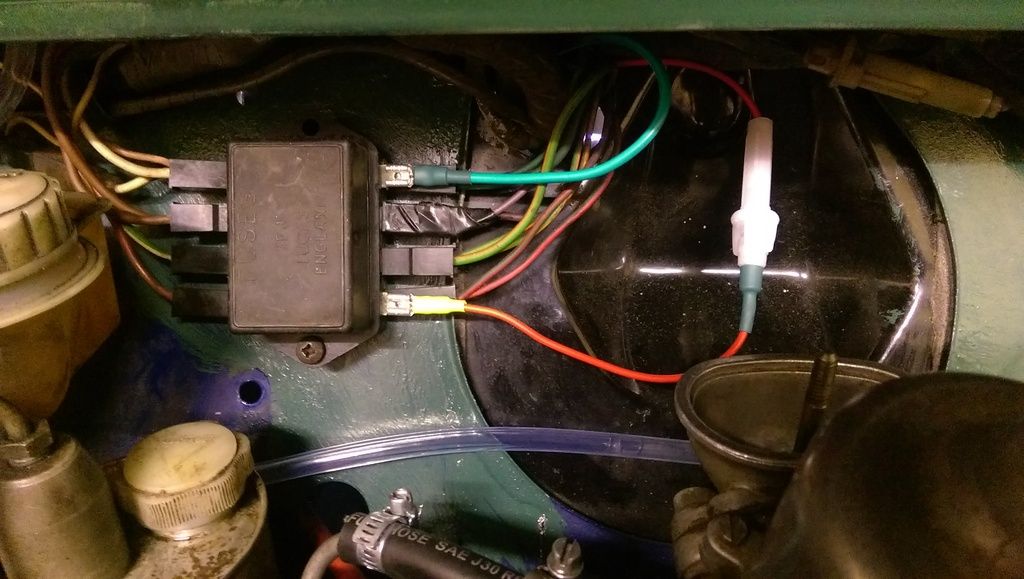
Disconnected the Negative on the battery before I disconnected the positive from the solenoid to avoid arcing. The after I removed the battery positive from the solenoid block I cleaned up some of the terminals. I also found that the solenoid block was loose so I nipped it up. The ignition coil was also loose (must have forgotten to tighten it up last time I played with it).
Once everything was clean I fitted the new cable:
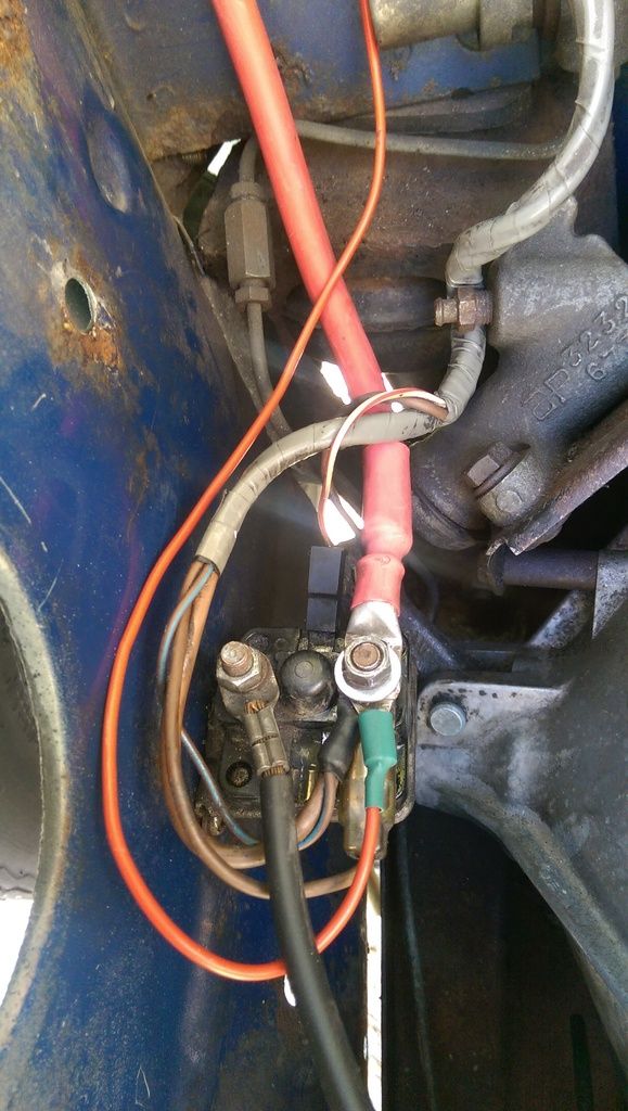
I weaved the cable alongside the loom and into the bulkhead thorough a hole left over from where I removed the Instrument Panel bracket:
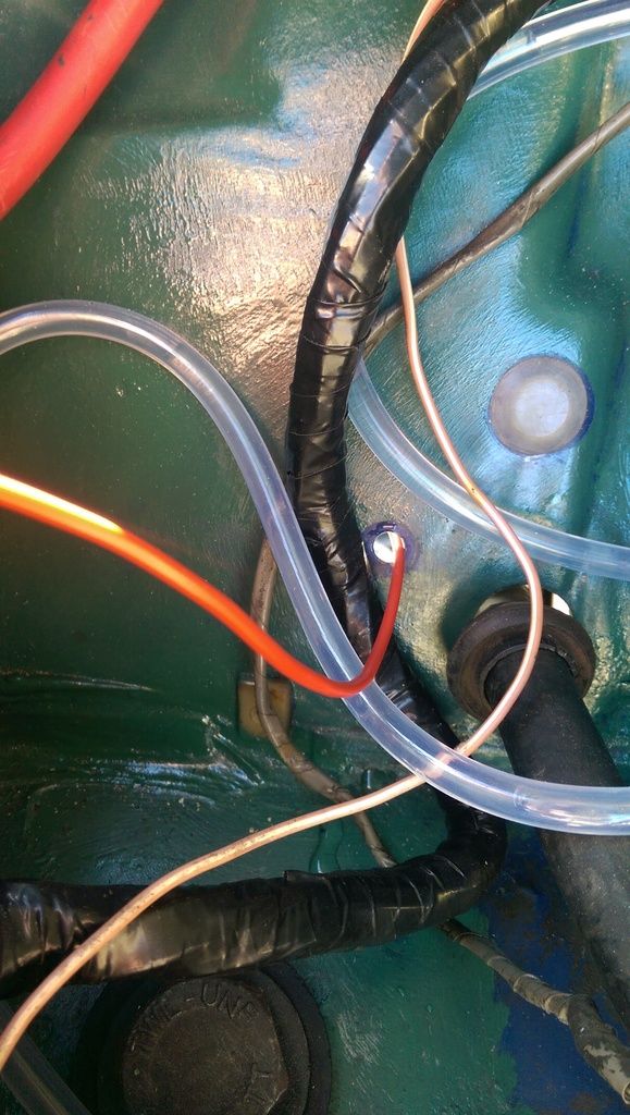
I fitted a grommet and wrapped the cable to the loom using black insulating tape. No pic yet.
After wrapping it all up I remembered that I need to fit an inline fuse DOH!! No worries as I'll fit it before it goes into the bulkhead as this is only a couple of feet from the solenoid anyway, anywhere else would be inaccessible.
I now need to find a switched 12v supply. I may use the one going to the radio as the cable is quite meaty, not sure where it picks up its feed though. I have seen that some people use a spare terminal from the fuse block?
Mill Road Garage
Posted 24 February 2017 - 08:46 PM
Use the second terminal up from the bottom of the fuse box on the left side as you look at it for your switched supply providing it's not got too much on it already
Up Into Fourth
Posted 25 February 2017 - 07:41 AM
Use the second terminal up from the bottom of the fuse box on the left side as you look at it for your switched supply providing it's not got too much on it already
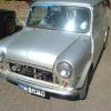
Thanks Ben, just found an old pic of my Fuse Box. The only wires that are missing from the pic are the purple ones that connect to the second down on the right hand side.
In the pic I can see that the left side second terminal up has a free spade 
And according to this this terminal is switched.
Any thoughts on where I should pic up power for my extra instrument lights, I guess they need to come on with the headlight switch. All of the bulbs on the back of the instrument panel are pushed into the plastic PCB so I need to find their supply? I guess this is from the fuse box also or the headlight switch?
Just looked at that link again and the bottom left appears to be Instrument Panel Lights so I'll pick up from there?
Edited by JonnyAlpha, 25 February 2017 - 07:43 AM.
Mill Road Garage
Posted 25 February 2017 - 11:12 AM
I believe the wires for the instrument panel lights are red with a green tracer (you will be able to check by looking at the wiring plug for the cluster)
Pick up the live from that and then run your earth to a suitable ground point.
Up Into Fourth
Posted 25 February 2017 - 12:45 PM
I believe the wires for the instrument panel lights are red with a green tracer (you will be able to check by looking at the wiring plug for the cluster)
Pick up the live from that and then run your earth to a suitable ground point.
Ben when you say 'pick up the live from that' do you mean from the spade on the fuse box or by cutting into the instrument panel lights cable behind the dash?
Up Into Fourth
Posted 25 February 2017 - 07:10 PM
Bit more time today even though the weather wasn't too good.
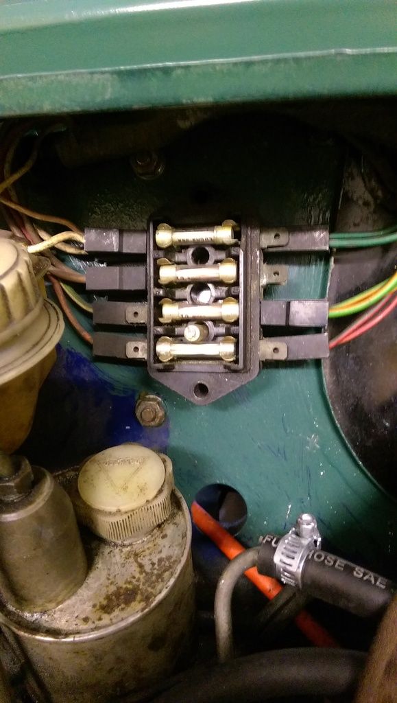
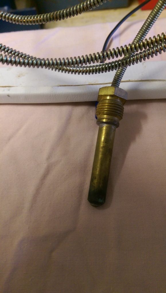
Fitted this Oil Temp Gauge but I can't install it at the mo as I need an Oil Filter adaptor but I'd like to thread it through the Bulkhead and wrap it up in there but I need to possibly dismantle it. Can I remove the sheathing from gauge? The Temp Sensor end seems to be fixed in place.
I started to wire up the lighting for the gauges, spliced some wire together, soldered it and fitted some heat shrink:
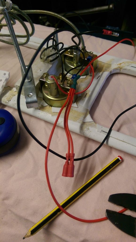
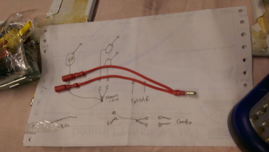
Also made up some 2 to 1 cables that I'll need to install the dash:
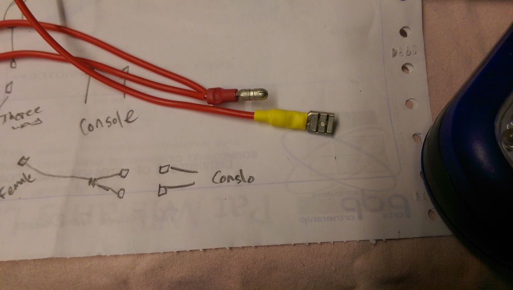
Then to pick up a feed from the Fuse Box I fitted a spade connector and again some heat shrink:
I found a feed for the Instrument Panel Lighting from the bottom R/H connector on the fuse box, this is annotated amongst other things as Instrument Panel Lighting. I also fitted an in line fuse with a lower rating for the lighting.
For my new switch feed for the Radio and In Car PC I ran a cable from the top RH side on the fuse box:
Once I had wired up as much as I could I started to wrap everything up with insulation tape:
I wired up the Panel Lighting and tested it and both my gauges lit up but the Rev Counter did not. Although the earth cable coming out of the Rev Counter was connected I think this may just be for the Rev Counter. I'll check the bulb but maybe the body of the gauge needs earthing?
Up Into Fourth
Posted 25 March 2017 - 09:24 PM
Bit of an update from the past few weeks.
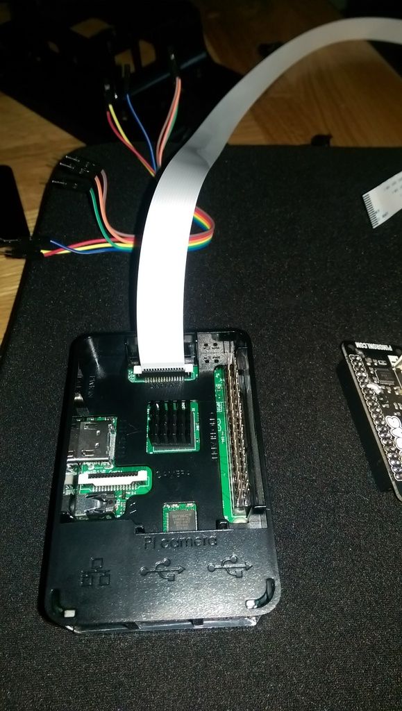
When I first fitted the In Car Entertainment System (Raspberry Pi PC and 7 Inch Screen) at first I opted to fit the Pi in the Screen:
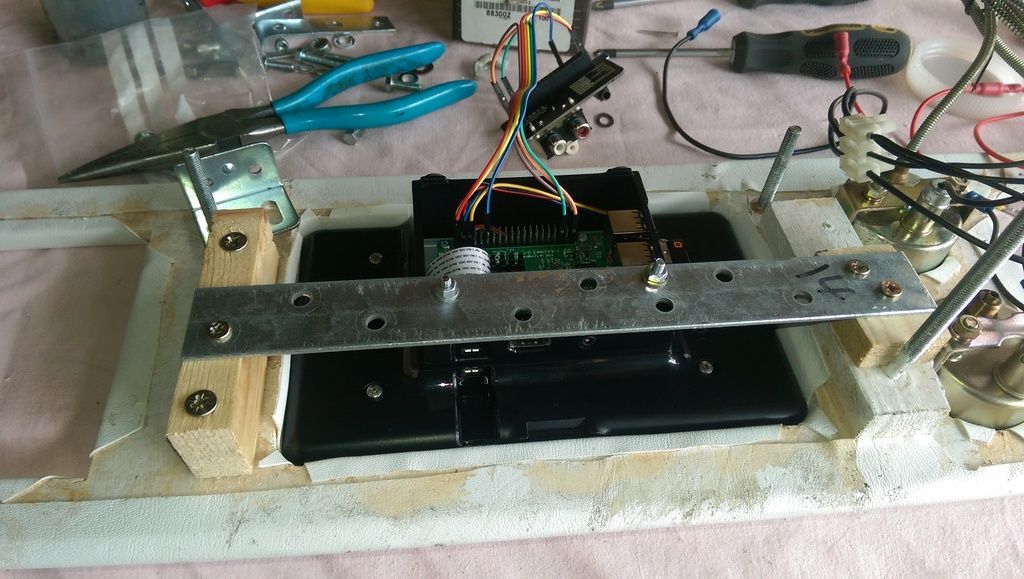
This turned out to be a problem because if there were any faults I would have to remove the dash!!
So I purchased a 75cm flat ribbon cable and decided to fit the Raspberry Pi PC in the glove compartment:
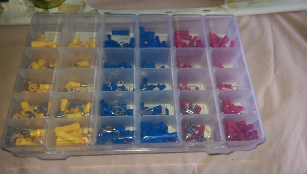
During the install I ran out of connectors so got these off of Amazon:
To fit everything in the glove compartment I had to cut some plywood to fit. Coated it with some primer:
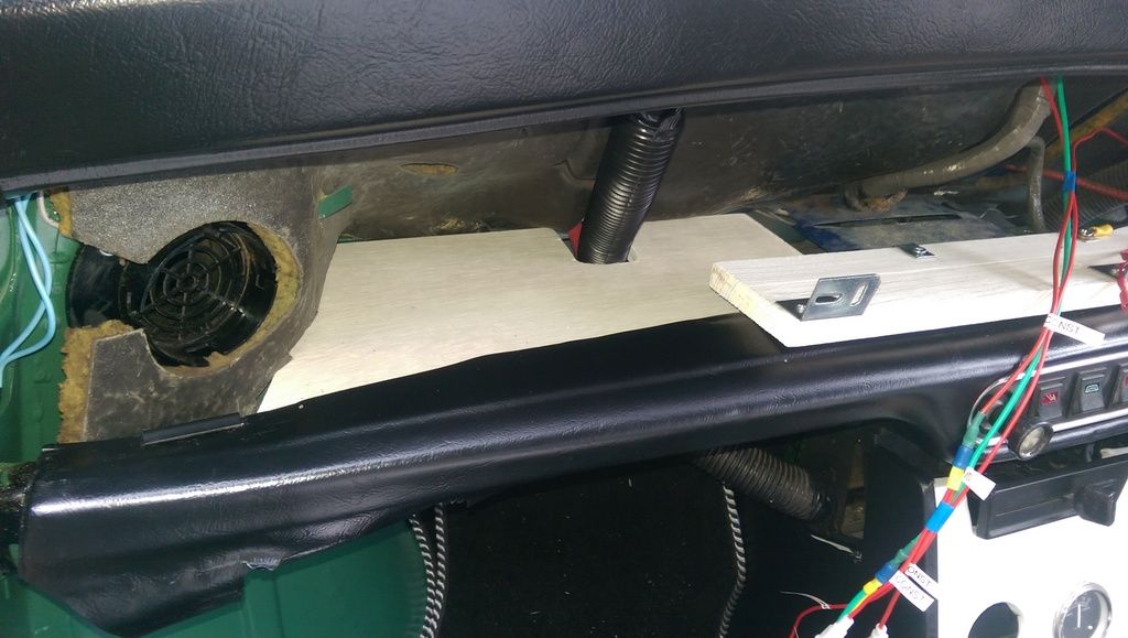
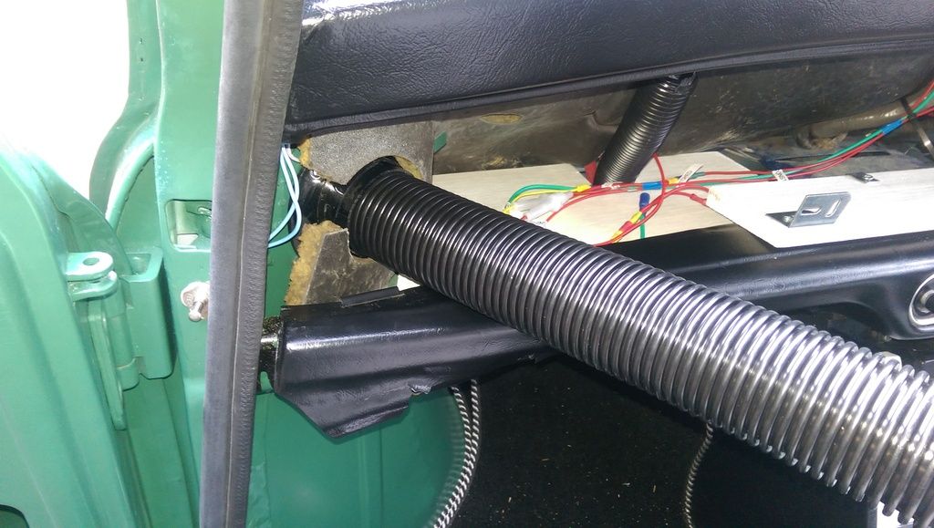
Tried some hose to connect up the vents - this was cut to length but it turned out that the vents don't line up anyway!!!
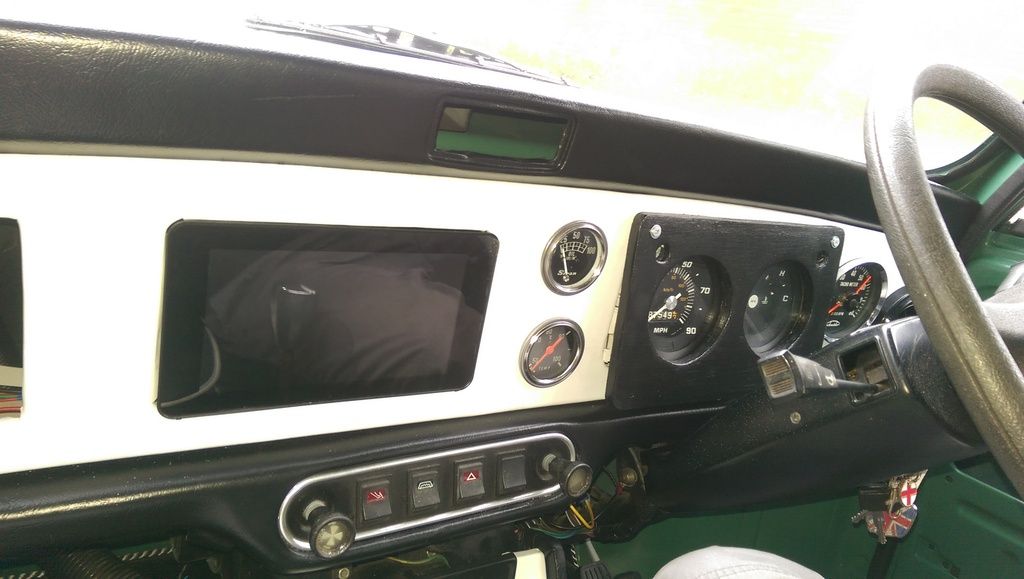
Main dash fitted with screen in place:
And then with the Instrument Panel fitted:
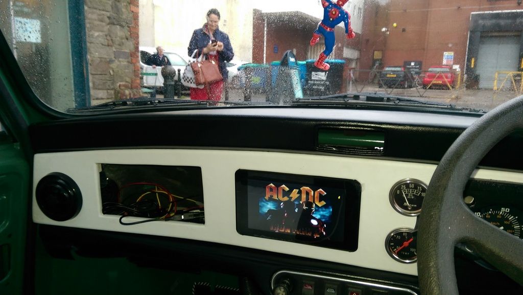
To get the angle for visibility I used some tap washers.
And here it is playing a music video (when stationary of course).
Still need to get an screen mounted aerial for the radio.
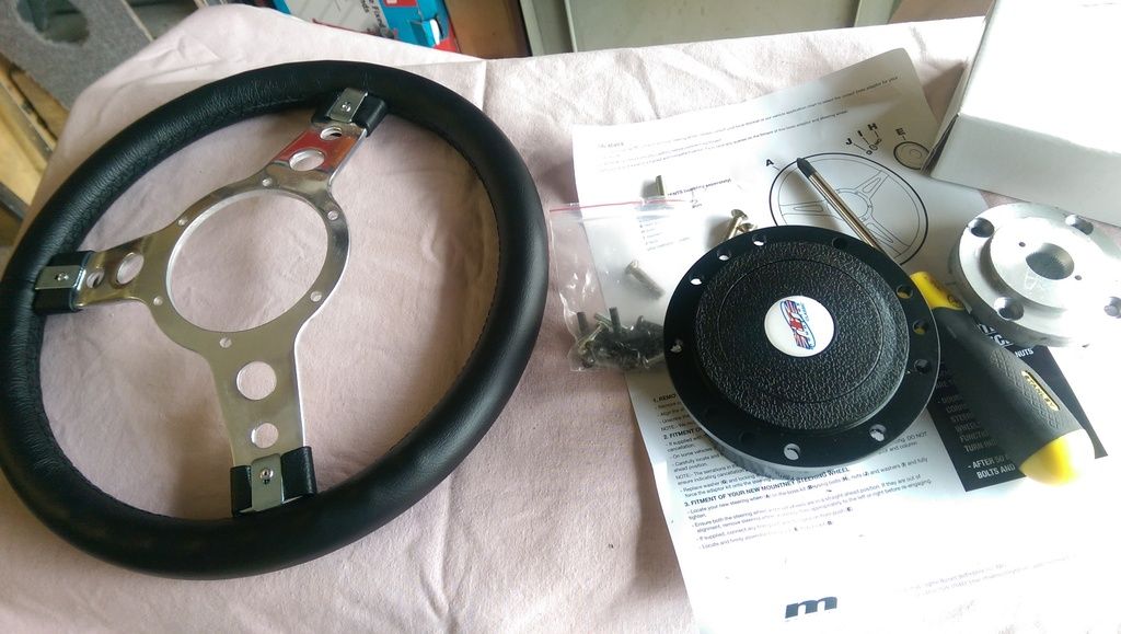
Then my birthday pressie arrived:
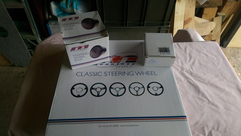
A nice 13 Inch Mountney Steering Wheel:
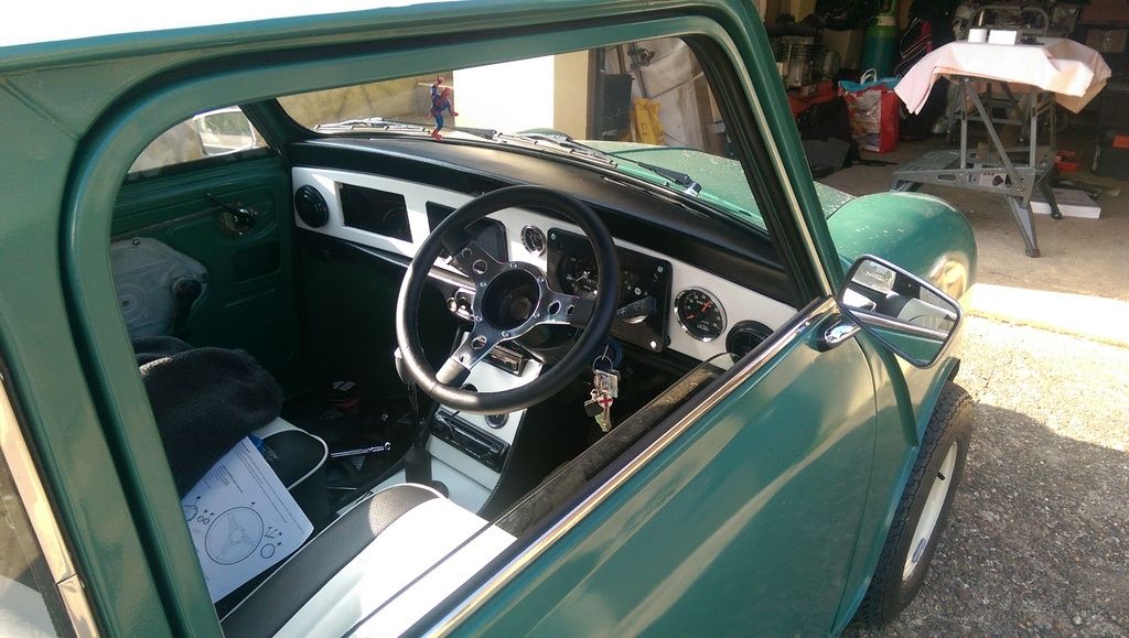
And here it is fitted:
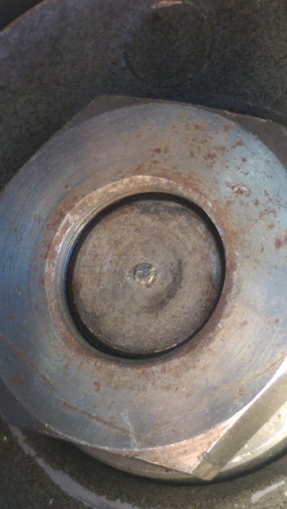
When I took of the centre nut there was no star washer in place (but you could see marks where one had been fitted previously).
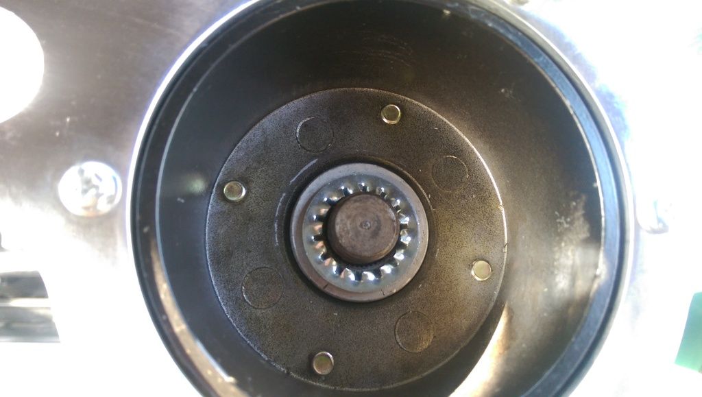
When I fitted the Star Washer and did the nut up (Torqued to 47nM) the nut does not completely sit on the column, will this be a problem - if so how do I fix it?
Up Into Fourth
Posted 29 March 2017 - 08:16 AM
While building the dash I found the following links handy (text and pics) in case anyone else is looking for info:
http://www.minifinit...php?f=6&t=73337
http://www.totalmini...cooper-spi.html
http://www.minifinit...php?f=6&t=52005
http://www.minifinit...p?f=186&t=91371
Edited by JonnyAlpha, 29 March 2017 - 08:16 AM.
Up Into Fourth
Posted 10 April 2017 - 09:21 AM
Didn't include a shot of the finished wheel, although I still have the chrome centre to fit.
Up Into Fourth
Posted 12 April 2017 - 08:30 PM
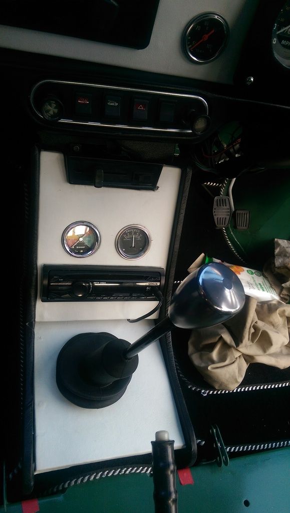
Managed to get the vacuum gauge fitted. It is not connected up but I do have a tube running from it into the engine compartment waiting to be connected. The ammeter is in and the light is connected but the ammeter is not wired up - I chose not to as its not the correct type so i'll replace it at some point with a volt meter.
I also picked up a windscreen antenna so I could get the radio working. So now I have a radio, In Car PC and CD player all running through the amplifier.
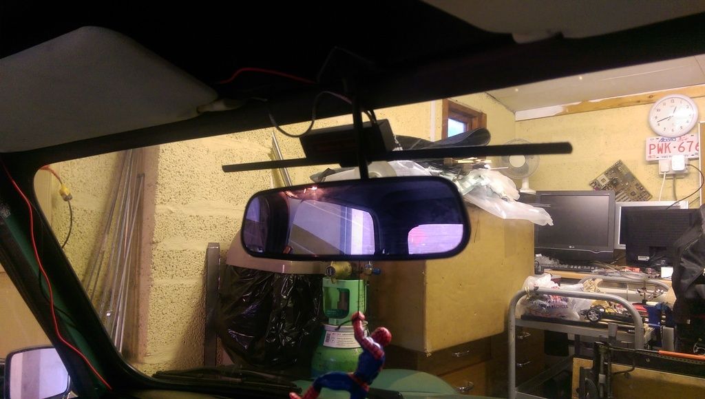
The antenna is wired up but I just need to tidy up the wiring.
If anyone is interested here is a blog I did on the In Car Entertainment Setup:
I am THE CLAMP MAKER
Posted 12 April 2017 - 08:36 PM
Looks great mate, I bought one of those ariels from halfords to, I ended up taking it apart just using the long strip which is mounted up under the top dash rail (+ an added arial wire inside the door rubber) with the majority of the arial cable, so you can't see it.
Mill Road Garage
Posted 12 April 2017 - 10:04 PM
I just read through your blog on building the system.
Very interesting.


0 members, 1 guests, 0 anonymous users


