Jump to content


Photo
- - - - -

Step By Step Engine Build, No Waffel, Just Building..


  • Please log in to reply
116 replies to this topic

#1 AndyMiniMad.

AndyMiniMad.

    Up Into Fourth

  • Members
  • PipPipPipPipPipPipPipPipPip
  • 3,290 posts
  • Location: Under The Bonnet.

Posted 26 November 2011 - 12:36 PM

Hi folks..some of you may have read my other thread where I did the same thing...but to be honest I think there should be a thread with JUST the engine build...Step by step factual stuff..Dont know if im going to be allowed two build threads on the go at the same time but hey ho!!

If you want general engine build info with loads of waffel then check out the other thread, but I would like this one to be just the build please..Of course you can feel free to make comments...but Im not changing the specs or fitting different cams ect ect...What you see is what you get..

So to start...

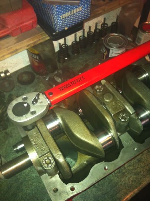
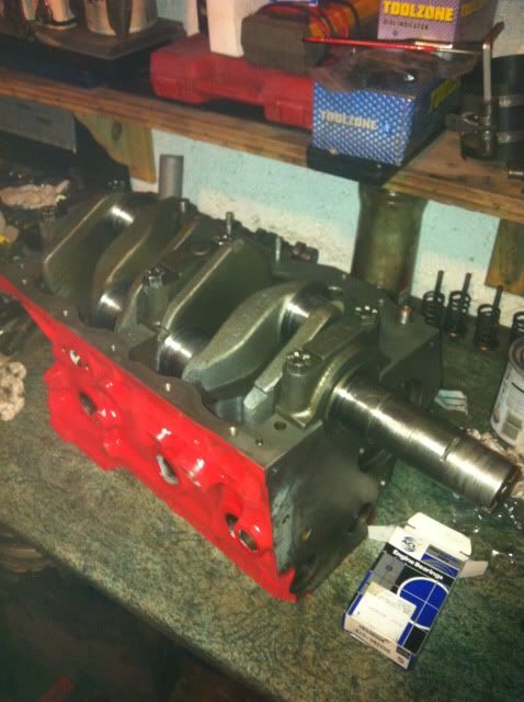
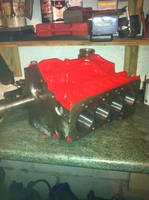
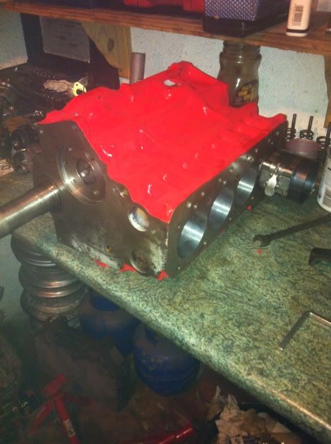
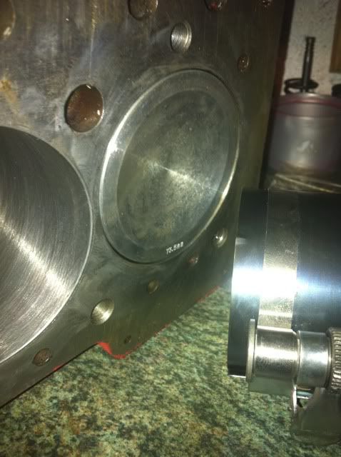
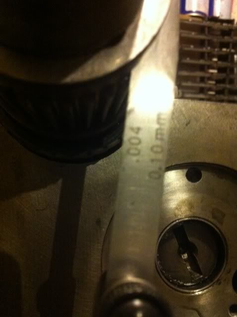
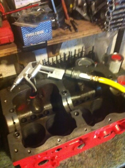
Here we have a newly bored 1275 block, its had the bores taken out to 73.5mm, im sure you all know thats 1380cc. Its had new cam bearings and they have been reamed to the cam size.

Posted Image

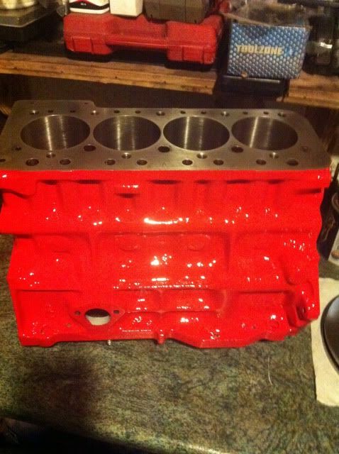
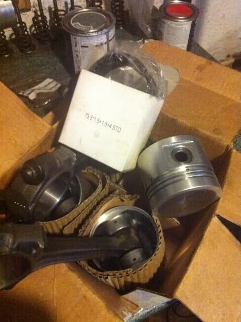
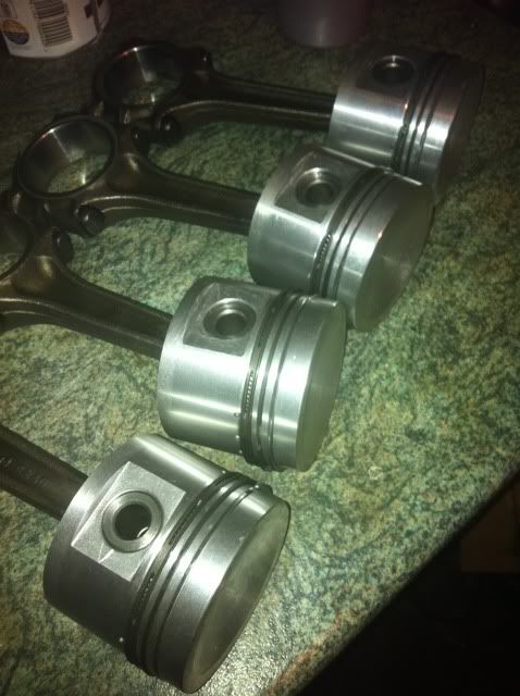
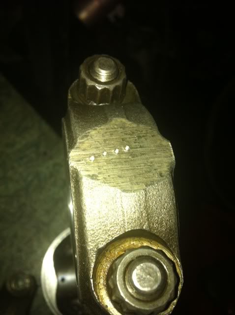
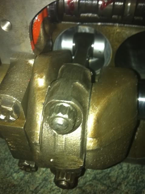
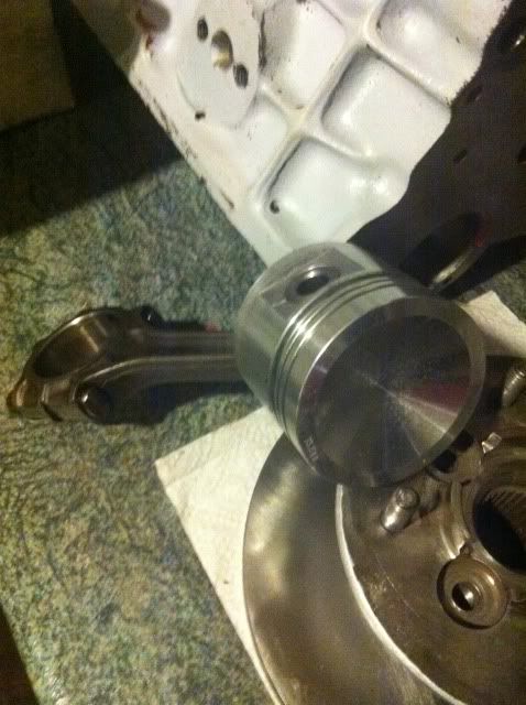
The 1380 pistons have been fitted to the rods which were end over end balanced..

Posted Image

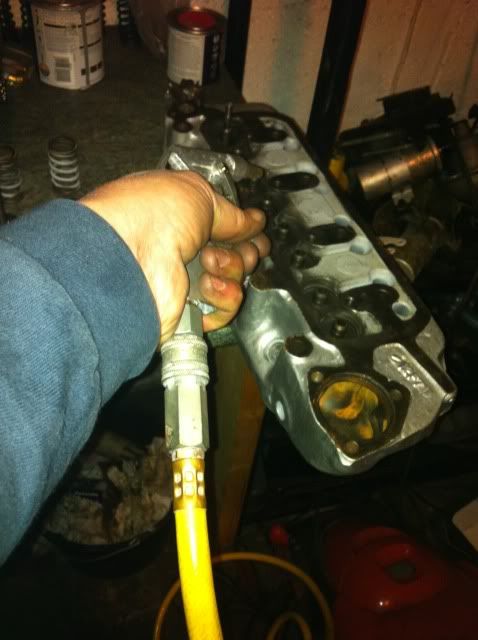
I cleaned the block thoroughly before starting, but because it had been left over night I gave everything a good blast with the air hose before starting, Yes some bits came shooting out of the oil galleries..so its always good to check.

Posted Image

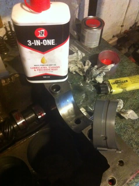
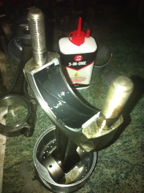
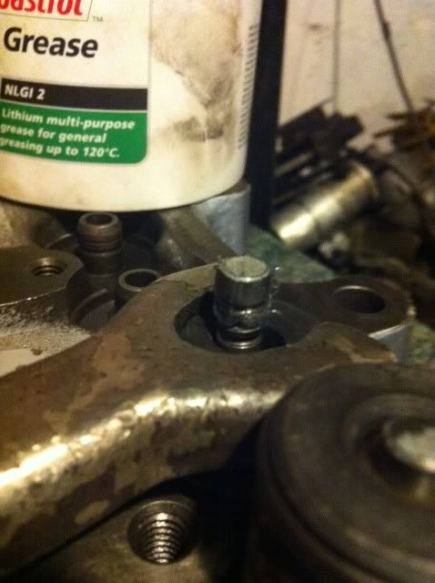
I use this stuff on all the bearings and followers. Its great stuff and really protects the bearings on initial start up..Its a bit messy though..

Posted Image

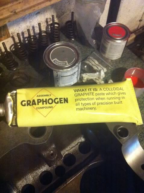
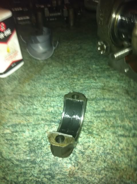
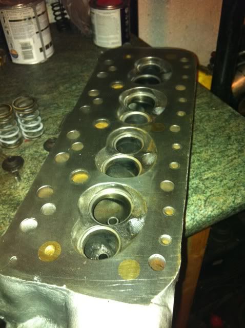
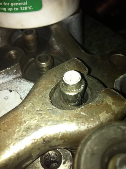
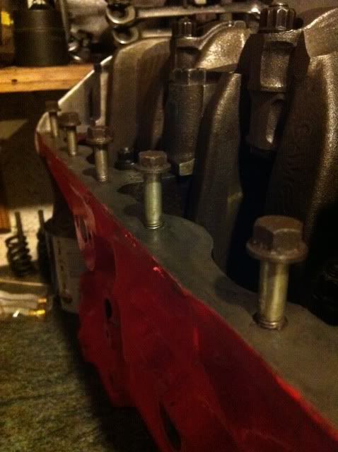
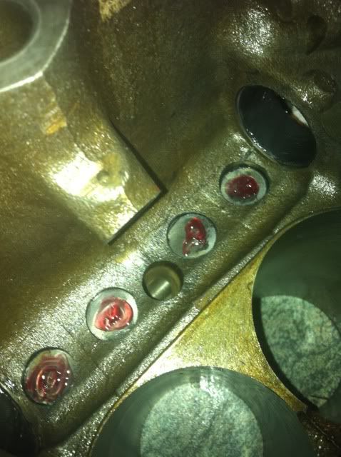
Right so once Im sure everything is spotless, I spread a small amount of the paste onto the new cam followers and smear it all around. ALWAYS fit new followers when building an engine they are only a few quid and its one of the major high wear points in the engine.

Once the followers are placed into the block, I use this stuff on the faces where the lobes rub.

Posted Image

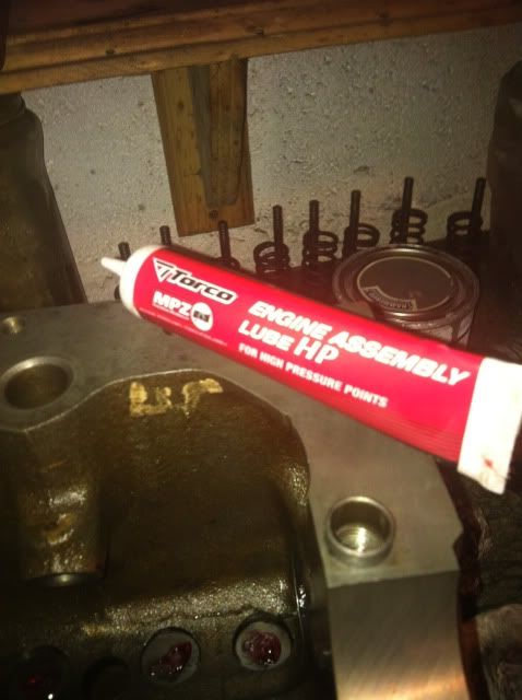
Its the same sort of stuff as the Graphogen. but is fomulated for the high wear points. At least thats what it says on the tube. It sticks to the lobes and followers and creats a sort of protactive film.

Posted Image

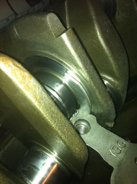
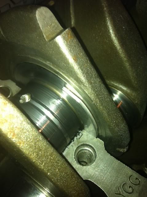
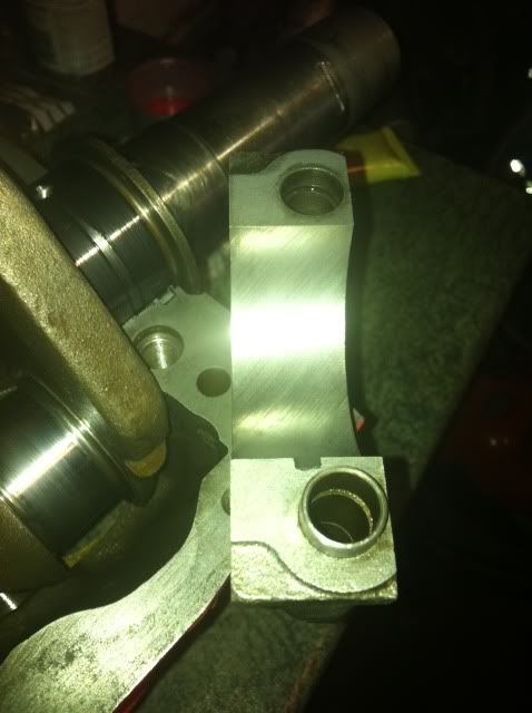
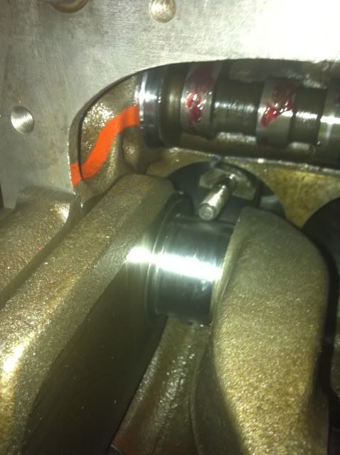
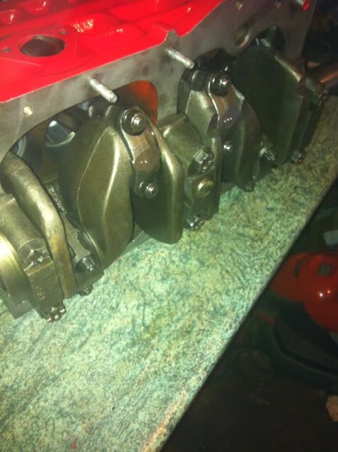
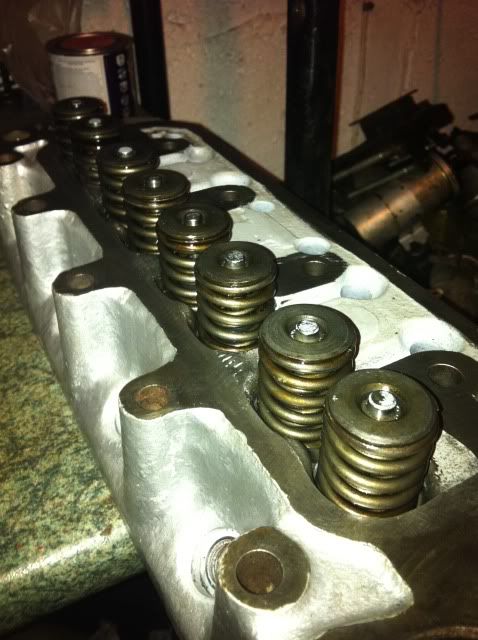
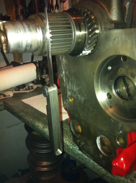
I was ultra carefull when fitting the MG metro cam, I moved it over the new bearings very slowly and made sure not to let it bang into anything. The bearings were given a smear of the Graphogen stuff..

Posted Image

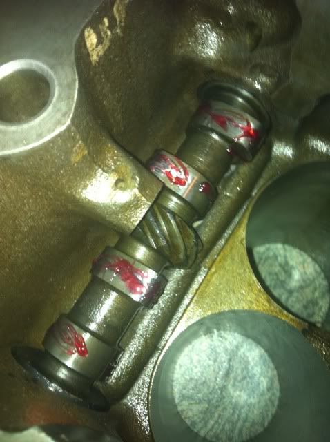
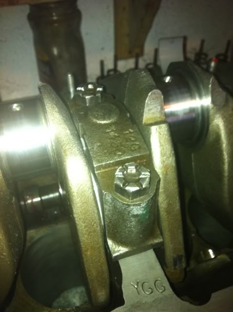
So there it is all fitted with the lobes covered in lube..

Edited by AndyMiniMad., 26 November 2011 - 12:40 PM.


#2 Bungle

Bungle

    Original Spamster

  • Members
  • PipPipPipPipPipPipPipPipPipPipPip
  • 28,971 posts
  • Location: Cornwall
  • Local Club: cornish mini club

Posted 26 November 2011 - 12:52 PM

thumbs up from me ;)

keep this going

#3 AndyMiniMad.

AndyMiniMad.

    Up Into Fourth

  • Members
  • PipPipPipPipPipPipPipPipPip
  • 3,290 posts
  • Location: Under The Bonnet.

Posted 26 November 2011 - 01:06 PM

So next it was time for the crank to go in..I had it checked and then spent ages cleaning it. Particularly the oil ways..a good blast with the air hose to make sure and its time to start.
First thing was to give the faces where the bearings sit a good clean with some 2000 grit wet and dry. then a smear of oil and the bearings can go in.

Posted Image

Once they were fitted I gave them a coat of the Graphogen and placed the crank very gently in possition.

Posted Image

I then gave it a couple of turns to make sure it was smooth on the bearings and fitted the new thrusts. They will go in very easy by just pushing them into the slots and turning the crank around. You can just see the end of this one as it goes in.

Posted Image

You can also see the paste has coated the crank journels as ive been turning it.

Next was to fit the caps..I placed the center cap on first after fitting the bearing of course, not forgetting the thrusts. these ones have the lugs which locate into the center cap.

Posted Image

Once the center cap was on I made sure the crank was still turning smoothly before torquing it down to 56nm. The crank should still spin freely with the cap torqued down. If it doesnt turn with just two fingers then something is wrong!

Next its time for the other two caps. All cleaned up. oiled, and ready for the bearing.

Posted Image

After each cap is fitted make sure the crank still turns freely. Then once you are happy set the torque wrench to 85nm and make the final turns. Do this in one movement of the wrench. It should only be a quater turn before it clicks..

Posted Image

Again check the crank is free to turn with two fingers and thats you done...Well for this bit anyway.

Posted Image

I will fit the pistons and post that bit tomorrow...

I hope this will be usefull to some people who are wanting to rebuild their engines...

Cheers

Andy..

#4 AndyMiniMad.

AndyMiniMad.

    Up Into Fourth

  • Members
  • PipPipPipPipPipPipPipPipPip
  • 3,290 posts
  • Location: Under The Bonnet.

Posted 26 November 2011 - 04:11 PM

I got one of the pistons fitted so thought I would do a quick update..

Here they all are with the rings.

Posted Image

I fitted the rings by spreading them over the pistons with my thumbs..I have a piston ring tool but prefer to do it this way as I can feel the tension better.

All fitted.

Posted Image

I turned the block on its side so I can get access to slide in the pistons. The bores have been cleaned again to make sure all the machine oil used when the rebore was done is removed. and then I used fresh oil down the bores.

Posted Image

I use the ring compressor to squash the rings after I had spaced the gaps evenly around the piston. I also used plenty of oil on the rings and down the bores.

Posted Image

The big end caps and rods were marked with a spot punch when I removed them. this way I know which one goes where and dont get things mixed up.

Posted Image

Posted Image

The bearings get the same treatment as the mains ones..

Posted Image

Im starting with number one so it goes in this end of the block..number one is always at the watwer pump end.

Posted Image

When sliding the piston down the bore make sure you line the big ends up with the crank journel...the rods are shaped to fit.

Posted Image

Then once you are sure everything is lined up gently tap the top of the piston with the handle of a hammer or similar untill it pops into the block...If it stops or wont go in DONT be tempted to whack it harder. This is where you will break the rings.

Posted Image

The caps get more Graphogen and on they go.

Posted Image

Once you have them on but not fully torqued up, turn the crank, If its tight then you have the cap on the wrong way around. Swap it round and try again. You will feel the difference..

Posted Image

So thats number 0ne fitted...the other three are just the same..

#5 Carlos W

Carlos W

    Mine is purple, but I have been told that's normal

  • TMF+ Member
  • PipPipPipPipPipPipPipPipPipPipPip
  • 10,110 posts
  • Location: Sittingbourne, Kent

Posted 26 November 2011 - 04:17 PM

Great pics!

#6 nafnaforiginal12

nafnaforiginal12

    Mini Mad

  • Noobies
  • PipPipPipPip
  • 282 posts
  • Location: Carlisle, Cumbria
  • Local Club: Cumbria Mini Cruisers

Posted 26 November 2011 - 04:38 PM

Great thread. I'll be following this closely.

Keep up the good work ;D

#7 Mini 360

Mini 360

    Up Into Fourth

  • Members
  • PipPipPipPipPipPipPipPipPip
  • 4,933 posts
  • Location: Aberdeenshire
  • Local Club: Independent

Posted 26 November 2011 - 11:08 PM

Brilliant Andy! Following this one closely for the 1275 in the garage which is awaiting rebuild :D

#8 The Matt

The Matt

    You don't escape that easily.....

  • Admin
  • PipPipPipPipPipPipPipPipPipPipPip
  • 17,229 posts
  • Name: Matt
  • Location: Overton, North Wales
  • Local Club: Welsh Border Minis

Posted 27 November 2011 - 08:08 AM

I've cleaned a couple of posts out of this thread. It's great that people put the effort into writing this kind of thing, so please keep any comments on topic. Matt

#9 AndyMiniMad.

AndyMiniMad.

    Up Into Fourth

  • Members
  • PipPipPipPipPipPipPipPipPip
  • 3,290 posts
  • Location: Under The Bonnet.

Posted 27 November 2011 - 03:37 PM

The other three pistons are now fitted and the big end caps have beed torqued to 45nm..

Posted Image

Then I checked the end float on the crank..I set up the DTI on its magnetic stand and adjusted the preload to 3 thou with the crank pushed all the way over to the water pump end. Once the preload was set I zeroed the gauge..

Posted Image

Then with a large flat blade screwdriver I levered the crank back towards the DTI...

Posted Image

Thats 0.05mm which converts to 0.00197"..Im pretty sure that 0.002"-0.004" is ok...Its as near to 0.002" as makes no difference...so im going to leave it..the crank turns really smoothly with no binding at all so im happy with it..But if anyone has any advice then im happy to adjust it..

#10 AndyMiniMad.

AndyMiniMad.

    Up Into Fourth

  • Members
  • PipPipPipPipPipPipPipPipPip
  • 3,290 posts
  • Location: Under The Bonnet.

Posted 29 November 2011 - 04:22 PM

Ok so the bits have not arrived yet so im a bit stuck with the block...however I have been working on the cylinder head...

This bit did arrive today so on it went..Its a blanking plate for where the old mecanical fuel pump fits. Going to fit an electric pump so wont need it,

Posted Image

Anyway on to the Head,

12G940 big valve head which has been ported as much as is possible...I can get my whole finger through the valve openings and into the ports...smoooooth...

Posted Image

As always everything gets a good clean and a blast of air through the water jacket. I have lapped in the valves and tested them by filling the chambers with petrol...no leaks over night even with the springs not fitted...a very good seal..

Posted Image

Posted Image

You know when to stop lapping when the valves have a nice grey rim that is even all the way round. the seats should look the same.
I checked the valve guides bu inserting a valve and then trying to wobble it about in the guide...these are spot on as the guides were replaced recently.

Posted Image

These are the springs im going to use on this head...Cooper S ones...I will fit new Stem seals to all eight valves.

Posted Image

Posted Image

So first job is to fit the guides for the smaller spring. these stop the small spring moving around and binding with the larger spring..

Posted Image

Then the valve goes in and a stem seal

Posted Image

Then the inner and outer springs..and top bit.

Posted Image
Posted Image

At this stage you will need a valve spring compressor..

Posted Image

I used a very small dob of grease in the collet grooves..

Posted Image

Then stuck the collets in. they are held in by the grease..

Posted Image

Then I released the compressor and the valve is fitted...here it is with all eight done.

Posted Image

Edited by AndyMiniMad., 29 November 2011 - 04:27 PM.


#11 AndyMiniMad.

AndyMiniMad.

    Up Into Fourth

  • Members
  • PipPipPipPipPipPipPipPipPip
  • 3,290 posts
  • Location: Under The Bonnet.

Posted 29 November 2011 - 04:30 PM

Then I fitted the rocker post rods useing the double nut method to tighten them down.

Posted Image

I took the rockers apart and fitted a couple of large washers to the midle two rockers. this put them directly over the valve and will reduce the amount of side load exerted. should help to prolong the guide life.

Posted Image

I also got these in the post today..

Posted Image

Thats the heater take off valve all fitted and this head is now ready for action..

Posted Image

Posted Image

Hope to get my primary drive bearings tomorrow. Ill fit the new core and oil gallery plugs later and post a few more pics..

Edited by AndyMiniMad., 29 November 2011 - 04:31 PM.


#12 The Matt

The Matt

    You don't escape that easily.....

  • Admin
  • PipPipPipPipPipPipPipPipPipPipPip
  • 17,229 posts
  • Name: Matt
  • Location: Overton, North Wales
  • Local Club: Welsh Border Minis

Posted 30 November 2011 - 01:27 PM

Really great thread Andy, keep it coming!

#13 AndyMiniMad.

AndyMiniMad.

    Up Into Fourth

  • Members
  • PipPipPipPipPipPipPipPipPip
  • 3,290 posts
  • Location: Under The Bonnet.

Posted 30 November 2011 - 08:25 PM

Ok so ive fitted the primary drive gear and checked the end float....Oopps!! 0.014. That's a bit on the big side!!


Posted Image


So I measured the primary drive thrust washer and it's 0.112..


Posted Image


So if the end float is 0.010 to big then I need a primary thrust at 0.120 to take up the slack..(Internet shopping)


Posted Image


Posted Image


Thats better!


So I fitted the new thrust washer with the heavily champhered side towards the block..


Posted Image


Next on goes the primary drive gear..


Posted Image


After it was built up again it was a tiny bit on the tight side so I gave the C washer a rub over some 2000grit wet and dry..


Posted Image


Then I fitted it all up again and measured with the feelers...A snug fit!!


Posted Image


But the resistance is not to tight and the end float is now spot on at 0.004..


Posted Image


So with that all sorted I looked out the bolts that hold the gearbox to the block and ran them through the threads..


Posted Image

#14 gaffersr53

gaffersr53

    Learner Driver

  • TMF+ Member
  • PipPip
  • 15 posts
  • Location: shropshire
  • Local Club: shropshire

Posted 01 December 2011 - 01:12 PM

I will also be following what you do, have just got myself a mini shell and now looking for a 1275 engine to buy and rebuild. cant wait for update

#15 jaydee

jaydee

    Crazy About Mini's

  • Members
  • PipPipPipPipPipPipPipPipPipPip
  • 8,565 posts

Posted 05 December 2011 - 04:35 PM

Hats off Andy, thats a lot of effort in taking pics for all the steps, this should be moved into FAQ IMHO
You should add pics also for the first start procedure!:)


0 user(s) are reading this topic

0 members, 0 guests, 0 anonymous users