Jump to content


Photo
- - - - -

Step By Step Engine Build, No Waffel, Just Building..


  • Please log in to reply
116 replies to this topic

#31 AndyMiniMad.

AndyMiniMad.

    Up Into Fourth

  • Members
  • PipPipPipPipPipPipPipPipPip
  • 3,290 posts
  • Location: Under The Bonnet.

Posted 16 December 2011 - 09:20 PM

Fantastic thread Andy! really well put together.

When you say set the DTI with a little preload i assume this means a small amount of pressure on the pin of the DTI thats touching piston/pushrod?

Keep up the good work!

Yes thats exactly right...sorry I maybe should hsve explained it better...

And a big thanks for all the nice comments, I feel all warm and glowy now...

#32 grahama

grahama

    Up Into Fourth

  • Members
  • PipPipPipPipPipPipPipPipPip
  • 2,442 posts
  • Location: Warrington
  • Local Club: None in my area !!

Posted 17 December 2011 - 10:35 AM

Hi,

have been following this thread closely, fantastic source of info. It's my Winter job !! I have seen the cam timing on utube also on a mini mania vid, exactly the same. I have a standars cam from a 998, how do I know what the timing should be for that, ie you talk about yours being 109 deg timed ???

Also what do do with the 109 deg figure, do you have to move the crank around to 109 deg, not quite getting this bit, :shy:

Graham

Edited by grahama, 17 December 2011 - 10:40 AM.


#33 AndyMiniMad.

AndyMiniMad.

    Up Into Fourth

  • Members
  • PipPipPipPipPipPipPipPipPip
  • 3,290 posts
  • Location: Under The Bonnet.

Posted 17 December 2011 - 10:47 AM

A standard 998 cam will be fine dot to dot...no reason to do cam timing on a non performance cam..but if you want to, then the timing for yours should be 106deg ATDC...referenced from Mr D Vizard..

Edited by AndyMiniMad., 17 December 2011 - 10:53 AM.


#34 AndyMiniMad.

AndyMiniMad.

    Up Into Fourth

  • Members
  • PipPipPipPipPipPipPipPipPip
  • 3,290 posts
  • Location: Under The Bonnet.

Posted 18 December 2011 - 11:54 AM

Right so iv got to the point where I need to shim the idler gear...Now some of you will say..But you should have done that when you had the block and gearbox apart...And you would be correct...However I thought I would show you how its done when your not splitting the engine and box as some people may need to do this without taking the engine completely apart..for example when fitting straight cut drops.

So I started by cleaning all the surfaces, accurate readings are critical! Then I used my depth guage to measure the gap in the transfer housing. I used a steel rule across the housing as a platform.

Posted Image

The depth turns out to be 1.008"

Posted Image

Next I measured the thickness of the gasket..

Posted Image

Its 0.032" which when fitted will sqwoosh down to 0.03"

The thickness of the steel rule is 0.08"

Posted Image

And the idler gear itself is 0.686"

Posted Image

So now we can calculate the shim thickness required by adding the depth of the housing to the thickness of the gasket

1.008 + 0.030 = 1.038"

Next we subtract the thicknes of the idler gear 0.686" and the thickness of the steel rule 0.08" from 1.038"

1.038" - 0.686" - 0.08" = 0.272"

So this is the thickness of the shims required to fill the rest of the gap..But we need and end float of 0.004" so Im looking for a couple of shims at 0.268"

Posted Image

Found a couple that are perfect...it doesnt matter if one is slightly thicker than the other so long as the total thickness adds up to whats required..

So thats me ready to put it all together..

#35 AndyMiniMad.

AndyMiniMad.

    Up Into Fourth

  • Members
  • PipPipPipPipPipPipPipPipPip
  • 3,290 posts
  • Location: Under The Bonnet.

Posted 19 December 2011 - 10:14 AM

Once I had fitted the idler gear I cleaned out the transfer housing and the gasket surfaces.

Posted Image

Then a bit of masking tape over the primary drive splines.

Posted Image

Im sure you lot know that this is to stop the splines damaging the oil seal as you fit the transfer case..I pressed in a new seal and placed the gasket on the case..

Posted Image

And then pushed the whole thing onto the engine...It should just slide on nice and smoothly, if it wont go on the last wee bit then dont be tempted to bash it on. just pull it off and try again. Its probobly the nose bearing not seating properly. Once its on I torqued the bolts up to 35nm.. Be carefull with the bolts as the ones that go into the block are a different thread than the ones that go into the gearbox...fine thread (block) course thread (gearbox).

Posted Image

The red plastic dust shield then slides over the primary drive and protects the oil seal..

Edited by AndyMiniMad., 19 December 2011 - 10:16 AM.


#36 AndyMiniMad.

AndyMiniMad.

    Up Into Fourth

  • Members
  • PipPipPipPipPipPipPipPipPip
  • 3,290 posts
  • Location: Under The Bonnet.

Posted 19 December 2011 - 05:09 PM

Ive cleaned up a flywheel, its a standard weight one, and fitted a new clutch plate.

Posted Image

Posted Image

I use an old Mains bearing to lock up the flywheel so I can tighten everyting up.

Posted Image

All fitted and the big nut torqued up to 203nm, (150lb).

Posted Image

I also got the cam nut torqued up to 90nm and bent the lock tab over..I cleaned up the wok and copper greased the plunger.

All together..Timing chain cover will be next, once ive cleaned and modified it...

Posted Image

Edited by AndyMiniMad., 19 December 2011 - 05:11 PM.


#37 Artful Dodger

Artful Dodger

    " I AM THE SPECIAL ONE"

  • Members
  • PipPipPipPipPipPipPipPipPip
  • 4,435 posts
  • Local Club: aint no body got time fo dat

Posted 19 December 2011 - 05:55 PM

coming together really nicely! il be using this as a guide to build my engine:) nice one andy!

#38 AndyMiniMad.

AndyMiniMad.

    Up Into Fourth

  • Members
  • PipPipPipPipPipPipPipPipPip
  • 3,290 posts
  • Location: Under The Bonnet.

Posted 21 December 2011 - 05:08 PM

A bit more progress... I have modified the breather on the timing chain cover and given it a good clean and a coat of paint..I cut the breather down its full length and removed all the gunk and gunge that was inside, then after a clean I welded a plate onto the front. I think it looks a bit better than bashing it flat with a hammer...but I suppose either way does the job!!
I also cleaned and refitted the water pump.

Posted Image

Then I refitted the oil presure relief valve..

Posted Image

Head studs refitted and a new BK 450 head gasket..

Posted Image

I carefully fitted the cylinder head and then the push rods.

Posted Image

Then on go the rockers, I made sure they seated onto the push rods properly and then fitted the locking plate before torquing the whole lot down...That plate is important as it holds the grub screw that secures the rocker shaft in place..

Posted Image

Its getting very close to going back into the car now.

Posted Image

#39 Mini 360

Mini 360

    Up Into Fourth

  • Members
  • PipPipPipPipPipPipPipPipPip
  • 4,933 posts
  • Location: Aberdeenshire
  • Local Club: Independent

Posted 21 December 2011 - 05:11 PM

Surprised you didn't paint the end of the block on the coreplug side where nothing connects to mate. Any reason as to why?

#40 AndyMiniMad.

AndyMiniMad.

    Up Into Fourth

  • Members
  • PipPipPipPipPipPipPipPipPip
  • 3,290 posts
  • Location: Under The Bonnet.

Posted 21 December 2011 - 05:23 PM

Good Point Andy....I was waiting till its in the car before painting it...For some reason I can never get an engine fitted without scratching that bit to death...

#41 AndyMiniMad.

AndyMiniMad.

    Up Into Fourth

  • Members
  • PipPipPipPipPipPipPipPipPip
  • 3,290 posts
  • Location: Under The Bonnet.

Posted 31 December 2011 - 04:07 PM

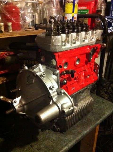
Right so this is the last job im going to do before fitting this engine in my red mini..

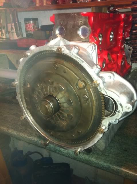
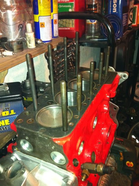
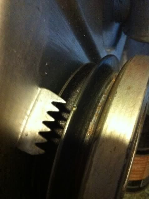
So I fitted the Harmonic damper..(fan belt pully), and because the engine was at TDC on number 1 bore the timing marks lined up spot on.

Posted Image

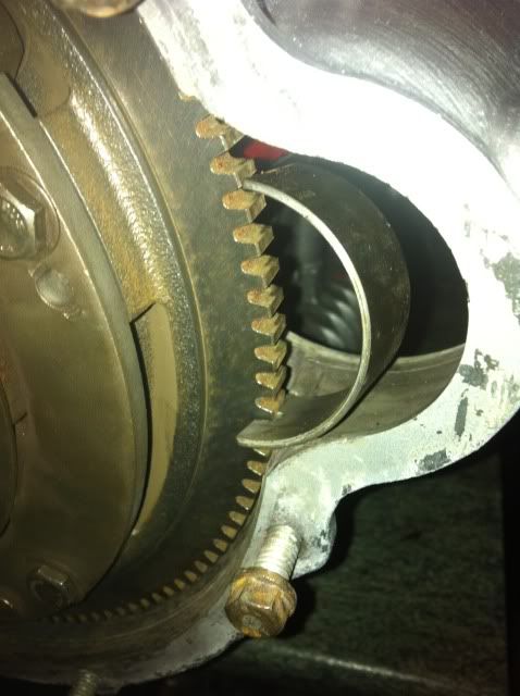
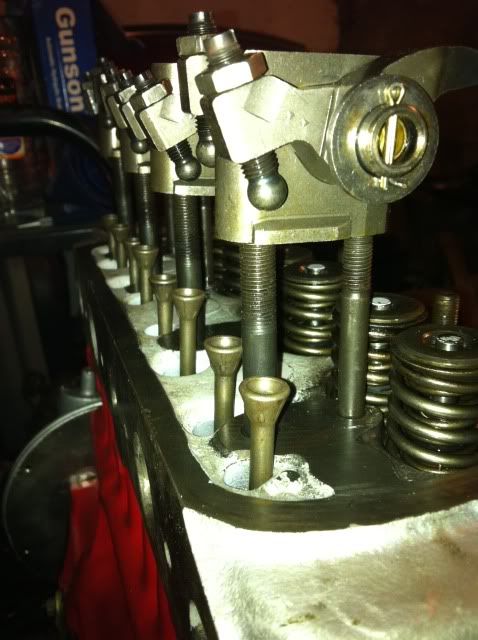
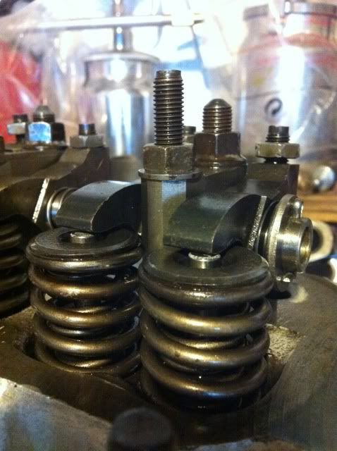
But just to be 100 per cent sure that number one is on the compression stroke I turned the engine through its cycle to see which valve opened first...Now as you all know the next valve to open after the compression stroke is of course the exhaust valve.Thats the one nearest the thermostat. So as I turned the engine over, sure enough the exhaust valve started to open. so I then wound the engine back to line up the timing marks. Both the valves on number one should be firmly shut.

Posted Image

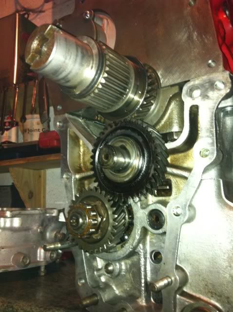
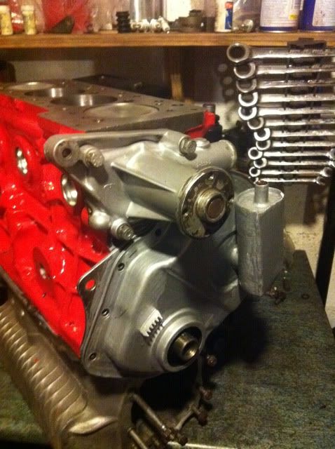
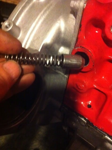
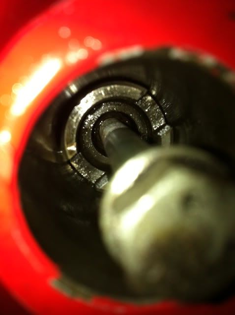
Next was to fit the dizzy drive spindle. I use a long bolt to fit this..

Posted Image

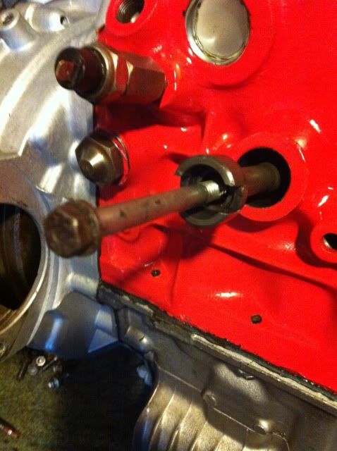
It needs to go in so that the groove is at the twenty to two position but due to the gearing on the spindle and the cam you need to play around a bit to get it spot on. I try to start it off at ten to four and then it just slides into position.

Posted Image

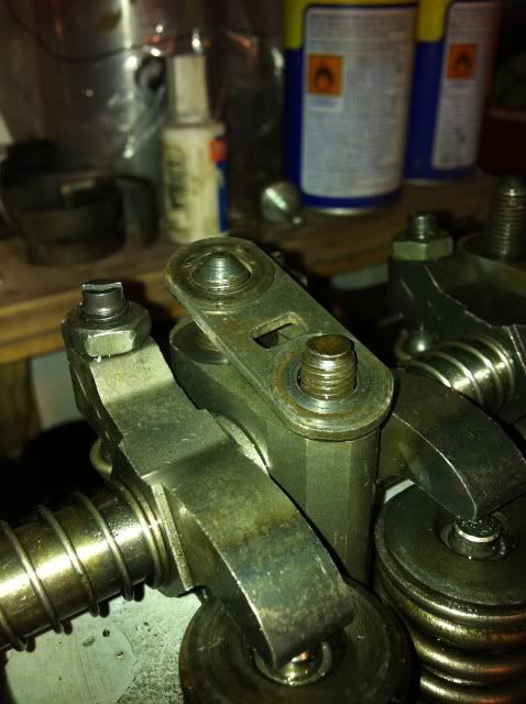
So then with the dizzy fitted you should see the rotor arm is pointing to one o'clock, this is the position on the cap that corresponds to the lead going to number one spark plug.

Posted Image

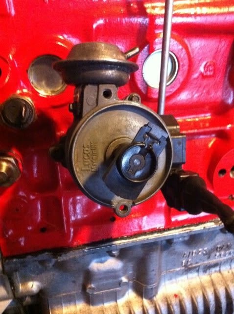
If its pointing to to seven o'clock then you need to remove the spindle, turn it through 180 deg and refit..

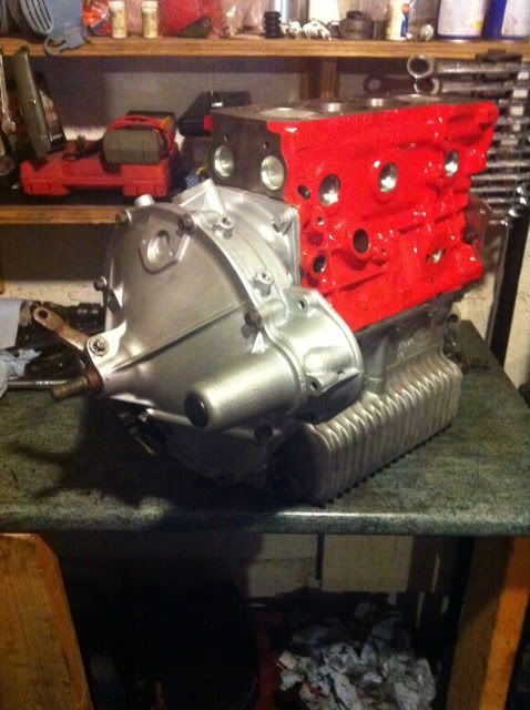
So thats it done..A 1380 with a big valve ported head...All standard everywhere else..I think the power will be around 75 at the wheels..maybe a bit more..but nothing to wild..just a nice every day driver..

Im not going to bother showing the fitting of the starter motor and other bits..but will post up a picture of the engine fitted in the car. and possibly a wee vidio of the first start.

Thanks for all the nice coments people have made during this build and also for not filling it with Spam..

Cheers

Andy

Edited by AndyMiniMad., 31 December 2011 - 04:11 PM.


#42 grahama

grahama

    Up Into Fourth

  • Members
  • PipPipPipPipPipPipPipPipPip
  • 2,442 posts
  • Location: Warrington
  • Local Club: None in my area !!

Posted 31 December 2011 - 07:40 PM

As I have said before, great thread, loads of info, could really be put to the top of the section as a guide. Even standard engines can be built using your thread.

Thanks a lot, as I have it all to do very soon !!!

Graham

#43 AndyMiniMad.

AndyMiniMad.

    Up Into Fourth

  • Members
  • PipPipPipPipPipPipPipPipPip
  • 3,290 posts
  • Location: Under The Bonnet.

Posted 31 December 2011 - 08:17 PM

As I have said before, great thread, loads of info, could really be put to the top of the section as a guide. Even standard engines can be built using your thread.

Thanks a lot, as I have it all to do very soon !!!

Graham


Thanks Grahama....I forgot to say in my earlier reply that the 109deg timing is the figure the cam is timed in at. it should only need adjusted if its more than a couple of degrees off the manufacturers figures. In my case they say 110deg is perfect so this is why dot to dot was fine as 1deg is nothing to worry about. If I wnted to make it perfect I would have either bought a 1deg offset woodruf key or adjustable timing gear..
I have another 1380 engine to build in a week or so and this one has a high spec cam and Duplex timing gear. I will add a bit to this thread to show how to adjust the vernier timing to get it bang on.

#44 jameslearwood

jameslearwood

    Super Mini Mad

  • Members
  • PipPipPipPipPipPip
  • 525 posts
  • Local Club: ALL ALONE

Posted 05 January 2012 - 05:01 PM

wow that is a superb thread loving the piccies, laptop will be in the garage during rebuild :D

#45 Old Bob

Old Bob

    TMF Menber Passed On R.I,P

  • Noobies
  • PipPipPipPipPipPipPip
  • 825 posts
  • Location: South Hams

Posted 10 February 2012 - 10:23 AM

Beautifully done Andy. A wonderful confidence builder for anyone - like me - contemplating re-building a series A to bring a tired engine back to life. I recently posed a question about the cost of offset boreing out an early block. Can you give me any idea about what I should expect to pay please?

Kind regards,

Bob


0 user(s) are reading this topic

0 members, 0 guests, 0 anonymous users