Jump to content


Photo
- - - - -

Home Brewed Micra Mini


  • Please log in to reply
184 replies to this topic

#1 micraminiman

micraminiman

    Mini Mad

  • Members
  • PipPipPipPip
  • 151 posts
  • Location: Scottish Highlands

Posted 02 August 2016 - 07:38 AM

Hi folks,

 Ive just bought an old 1998 Micra Si, and have begun putting the CG13 engine into my old Mini.


I will be using the full Micra wiring loom and clocks etc.


Have started by making a jig, and cutting away parts of the old subframe.


I have bought Landrover mounts and a Nippon Denso Alternator to begin with.


Waiting on cutting discs coming home now before I can do much more.


Any information and help is very much welcomed as I go along.


Thanks.

Attached Files


#2 McMini 22

McMini 22

    Mini Mad

  • Members
  • PipPipPipPip
  • 289 posts
  • Location: East lothian

Posted 02 August 2016 - 08:47 AM

Hope you don't mind me saying but your jig needs a bit more bracing.  Ideally before you cut all the front of the subframe off!


Best advice I can give is to read through all the other build diaries on here and 16v mini website.  When you come up against a problem look at how others have solved it and choose the solution that is best for you.  And don't be afraid to try something different.  You will get loads of help from both the forums.


It's good to see another one get started.  Keep at it, even when the going gets tough as there is light at the end of the tunnel and keep telling "yourself that others have done it, so can I".


Good luck.


#3 micraminiman

micraminiman

    Mini Mad

  • Members
  • PipPipPipPip
  • 151 posts
  • Location: Scottish Highlands

Posted 02 August 2016 - 09:24 AM

Hi there, Thanks for posting. Another Scot too I see!

 There is a cross brace of 40mm box thats been cut off at the bottom when I took the photo, between the posts. Just my awful photo skills with my phone... Its solid as a rock.

Ive been reading, and studying loads of pics for a while now, but some bits are still unknown to me so far. Had to machine the tensioner assembly for the water pump belt today to get it to fit in next to the tower better. 


 My mincer has been off the road for the last 12 years now, and I fully rebuilt the shell about 4 years ago and left it sat without an engine since then. All I knew was that I didnt want to put the A Series back into it, and whatever I chose had to fit under the standard front! It has a removable steel flip front that hinges forward too.

 I think the Micra is a good choice for me right now, and an enjoying getting back into working on the Mini again as its been left these last few years as a painted rolling shell sitting looking poorly at the back of the garage.


 Cant wait to get it all done, hoping for next Summer of fun in the old Mincer again, relive some memories with a more modern engine....


#4 micraminiman

micraminiman

    Mini Mad

  • Members
  • PipPipPipPip
  • 151 posts
  • Location: Scottish Highlands

Posted 02 August 2016 - 09:33 AM

Pics when I was making the jig. You can see that its a full solid 40mm box jig. It was just roughly made as its only a jig, but the pickup points are sound and solid. I used two triangular lugs for holding the floor mounts, tapped out to M8. The front Tie rod mounts are tapped M8 through brass turned bushes that fit the mounts and into the box section.

Attached Files


#5 micraminiman

micraminiman

    Mini Mad

  • Members
  • PipPipPipPip
  • 151 posts
  • Location: Scottish Highlands

Posted 02 August 2016 - 01:23 PM

post removed as original belt tensioner not required......


Edited by micraminiman, 02 August 2016 - 08:02 PM.


#6 fuzzy-hair-man

fuzzy-hair-man

    Mini Mad

  • Members
  • PipPipPipPip
  • 181 posts
  • Location: Armidale NSW
  • Local Club: Minis in the Gong

Posted 02 August 2016 - 02:43 PM

Most conversions use the alternator to tension the belt and run the alternator and waterpump from the same belt.


Not saying you have to or even should but it does buy some more room.


Are you thinking of putting the alternator in the guard or up behind the head?


#7 micraminiman

micraminiman

    Mini Mad

  • Members
  • PipPipPipPip
  • 151 posts
  • Location: Scottish Highlands

Posted 02 August 2016 - 03:22 PM

Going to front mount the Denso alternator, but that can all change! That's why I'm posting here, to summon the knowledge of the forum.

#8 micraminiman

micraminiman

    Mini Mad

  • Members
  • PipPipPipPip
  • 151 posts
  • Location: Scottish Highlands

Posted 02 August 2016 - 03:22 PM

Ive now looked at other builds and their single belt ideas, and that it indeed the way to go.


Some more chopping out of subframe at the diff cutout tonight has allowed the engine to sit in nearly the right place for the first time. A bit more cutting and it will be in place.

 Thanks for the help, its already proved to be very worthwhile to me. Anything else I need to know before I make a mess of things?

Attached Files


Edited by micraminiman, 02 August 2016 - 08:01 PM.


#9 McMini 22

McMini 22

    Mini Mad

  • Members
  • PipPipPipPip
  • 289 posts
  • Location: East lothian

Posted 02 August 2016 - 10:53 PM

Your main clearance problems are water pump to tower and the differential to steering rack. You will need the subframe and the engine in the car to see the steering rack clearance.
What is your plan for the subframe?

#10 fuzzy-hair-man

fuzzy-hair-man

    Mini Mad

  • Members
  • PipPipPipPip
  • 181 posts
  • Location: Armidale NSW
  • Local Club: Minis in the Gong

Posted 03 August 2016 - 01:19 AM

It looks to me like your engine could come over to the driver's side a bit, most people including me cut off that lug on the waterpump housing as it does nothing.


This buys some more room between the radiator and the dizzy and importantly makes the short driveshaft not so short.


Some (including me) use the original mini subframe driveshaft holes (some fiddling involved) so that could give an idea how far you can move the engine back,

I still ended up spacing the grill forward and trimming the front panel a bit.


#11 micraminiman

micraminiman

    Mini Mad

  • Members
  • PipPipPipPip
  • 151 posts
  • Location: Scottish Highlands

Posted 03 August 2016 - 07:19 AM

Great advice guys, thanks. I will look into moving the engine over a bit tonight and see how it looks. I will also chop the lug off as you recommend. 


The other thing that bothers me is getting the height of the engine in the new frame right. I fear my Jig is too high at the bottom and not allowing me to drop the engine a wee bit further.


I dont suppose anyone has pics of their engine actually finally mounted in the frame, but off the car so I can reference the location better?


Shingler made a frame that I really liked the look of. He had the bottom bars going around the sump, so it wasnt too low under the engine, and two bars to the towers like brace bars. It looked very neat in its design. I will be using 25mm box section for the frame itself.


Edited by micraminiman, 03 August 2016 - 07:22 AM.


#12 McMini 22

McMini 22

    Mini Mad

  • Members
  • PipPipPipPip
  • 289 posts
  • Location: East lothian

Posted 03 August 2016 - 09:21 AM


Great advice guys, thanks. I will look into moving the engine over a bit tonight and see how it looks. I will also chop the lug off as you recommend. 


The other thing that bothers me is getting the height of the engine in the new frame right. I fear my Jig is too high at the bottom and not allowing me to drop the engine a wee bit further.


I dont suppose anyone has pics of their engine actually finally mounted in the frame, but off the car so I can reference the location better?


Shingler made a frame that I really liked the look of. He had the bottom bars going around the sump, so it wasnt too low under the engine, and two bars to the towers like brace bars. It looked very neat in its design. I will be using 25mm box section for the frame itself.

Strangely enough I should be fitting my engine and subframe together in my jig either tonight or tomorrow night so that I can do a final clearance check and make up my driveshafts.  I will grab a few photos.


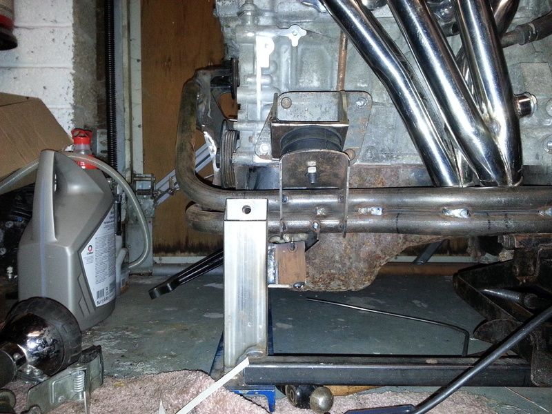
Here is all I have at the moment.

20160123_002506.jpg


#13 micraminiman

micraminiman

    Mini Mad

  • Members
  • PipPipPipPip
  • 151 posts
  • Location: Scottish Highlands

Posted 03 August 2016 - 10:57 AM

Thanks very much, this will be incredibly helpful to me. Your fine pic shows me that it does need to go over to the drivers side a wee bit, but also that my height isnt too bad at all.

 Pics that are taken square onto the engine from either side and front and back, like the one above are the real money shots. Likewise looking straight down on each tower.  This will allow me to gauge where it sits in relation to the towers and other reference points I can use so I can make up the frame. The final siting and mounting make-up will then be done with it on the shell.


And now lets blether aboot yer frame!  I really like the tubular idea, and also the way you took the lower bars up higher. I really dont like the way that some frames are going underneath the sump. Youve done good! And what did you use to clean the engine? Yers looks spotless. You can see the state mine is in... :-(


Edited by micraminiman, 03 August 2016 - 10:58 AM.


#14 McMini 22

McMini 22

    Mini Mad

  • Members
  • PipPipPipPip
  • 289 posts
  • Location: East lothian

Posted 03 August 2016 - 02:11 PM

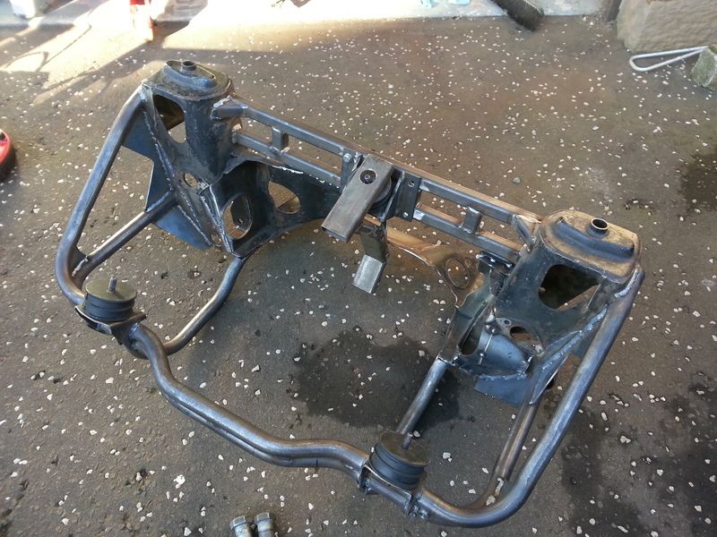
20160210_122026.jpg


My frame now does have bars underneath!  Figured it was better to hit the speed bumps with the frame than with my (new) sump.


Side to side position

The further to the right of the car the engine is will give you a problem with the right hand tie bar and the sump.  Mine clears by a gnats chuff!  The further to the left of the car means your left drive shaft will be short and you have gearbox clearance issues with the frame (depending on your frame design).


If you open any of my photos in a new window it should let you into my photobucket library.  Feel free to have alook through as I lost my original build diary when the server crashed for the 16v Mini Forum.


The tubular frame was only because I could access a pipe bender and some old steam pipe.  It made things a lot more complicated to fabricate but at the end of the day I'm very happy with how it looks.


The engine is not as clean as it looks in the photo.  I tried some caustic soda and it took all the muck off but left a chalky deposit of aluminium oxide.  I am just about to buy this

http://www.ebay.co.u...sd=191915375279


I will hopefully paint my engine, gearbox, subframe and engine bay next week so I'll let you know how it works.


Edited by McMini 22, 03 August 2016 - 02:12 PM.


#15 fuzzy-hair-man

fuzzy-hair-man

    Mini Mad

  • Members
  • PipPipPipPip
  • 181 posts
  • Location: Armidale NSW
  • Local Club: Minis in the Gong

Posted 03 August 2016 - 02:24 PM


Side to side position

The further to the right of the car the engine is will give you a problem with the right hand tie bar and the sump.


True;

It sounds dodgy but the sump to tie rod clearance can easily be solved with a BFH and bash in the sump a bit to clear... (how I did mine)

I've seen (in the flesh) a sump that was cut away as well as when my sump was off and there's a fair amount of room to spare. I'd rather that than tangle with driveshaft clearances on the other side.

Micraminiman you should have less issues with driveshaft clearance because you've got rid of the front half but the shorter the shaft the more angle to deal with any misalignment or just suspension travel.


Oh there's a couple of pictures on my thread of how things line up, and plenty of others who have done it before mine...


Edited by fuzzy-hair-man, 03 August 2016 - 02:25 PM.


1 user(s) are reading this topic

0 members, 1 guests, 0 anonymous users