Take your standard loom, strip it, remove all non-essential and superfluous wiring then rebuild using better heat shrink and wrap.
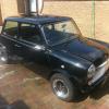
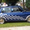
Nope... for a start a standard wiring harness will not actually fit in my car, it is not your run of the mill mini, it has seen an extensive range of modifications to the body and the components fitted, the only original mini electrical components are the wiper motor, steering column stalks & the light fittings.
It runs a polestar HS management system, ignition only at the moment, but the harness will have the wiring to literally plug & play for a closed loop injection system for up to 4 injectors.
The standard wire used in minis is barely fit for road car use let alone in on track conditions & the connectors are even worse. How many of you have had to wiggle a connector to get the headlights to work properly?
If you want a loom for track and race mini's then give John at Snetterton speed shop, he can give you a nicely made loom and control panel that he uses in his FIA cars that runs just the basics needed.
Great weight saving and professional and at a fraction of the cost of tools alone
I can't see where your gonna need more than 2 multi pin connectors, any more than this is just unnecessarily weight and even the best ali and plastic deutsch connectors fail
I used to work doing wiring looms and telemetry for such F1 cars, areospace and such projects although I have most of the gear.
Tools cannot be bought cheaply and if you do then they are total ******* and will mess crimps up.
Expect to pay 400-600 for crimp tool( you'll need two as pin and sockets use different tool, correct pin/socket adapters costing around 30 quid each depending on different sizes.
Boots will need filling with s11, you can mix it by hand but never works perfectly so ideally need to buy rs mixing gun.
For boots you'll also need an adjustable very high temp heat gun.
Strippers you can get some cheaper awg strippers for 150-200quid but after 400 strips we found we had to send away for resetting.
Hope your used to doing service loops in DR boots as this is a ******* to learn correctly, I used to grind down different size punches to help start
Also don't forget your lacing cord and kevlar thread, you'll need good teeth as they becom your third hand for tying up service loops and when twisting wires together ( you don't twist wire when sleaving, you use your open hand to braid the wires together passing wires between each finger)
Thanks Holmesy technical advice is what i am looking for. The decision has been made to build a harness to this spec, i didn't come here to be told not to do it.
I hear you on using the correct crimping tools, i think that is why i have so many problems with my existing wiring, with pins not retaining in the connectors, wires pulling out of terminals etc. I can get the correct crimp pliers for £270 and the turret for the Souriau pin & socket terminals for £100(both terminals use the same turret), i believe the plier frame can also take the turrets for deutsch DT & DTM connectors.
So i own a pair of "ideal" strippers for Teflon coated AWG wire (not the specific ones for Spec55) but can get the correct blades, i will try stripping the wire with the blades i have before i spend out on the 55-1987 blades. I don't yet have any experience in wiring service loops in this type of connector but i have had limited experience in larger industrial connectors, space is less of a premium here but the principal is the same, i've just ordered a cheap set of punches from ebay to help out.
Ive not heard of the s11 epoxy before, i had planned on using Resintech RT125, i already have the mixing nozzles and the 3M applicator gun. how does the s11 compare with RT125?
At the moment it looks like i'll need around 3-4 multi pin connectors to pass through the bulkhead, one connector with size 16 terminals for high current noisy ECU circuits (injectors, ignition coils, power feeds etc), another with size 20 terminals for ECU sensor wiring etc, then the chassis wiring which might all be in one connector or may have to be split between the high current circuits and low current circuits.
There will be one connector with size 20 terminals that will connect the rear harness to the power distribution/circuit breaker panel and a handful of 4-12 pin connectors for sensors, injectors, ignition coils, stack dash display etc. these will mostly be DT/DTM series with the exception of the injectors which will be Souriau (due to the fact that the connector will be fitted with a blanking cap until the addition of the injection system).
I know John and I am aware of the harnesses made at SSS, but i will not spend my money there, i have my reasons for this but i am not prepared to discuss on an open forum.
The other thing is that the harnesses made by john are mostly an off the shelf setup for FIA historics, my harness is somewhat more complicated than the minimalist setup of a FIA Historic.
As people have said this is a massive undertaking and is very time consuming to plan out, i am almost finished with the planning stages now, i have ordered everything apart from the souriau, DT/DTM connectors & the heatshrink boots, the mock-up sections have all been made and are due to be transfered to boards in order to start laying the wiring out in the next few weeks.
I am happy to share my progress on here if anyone is interested in how its all done?