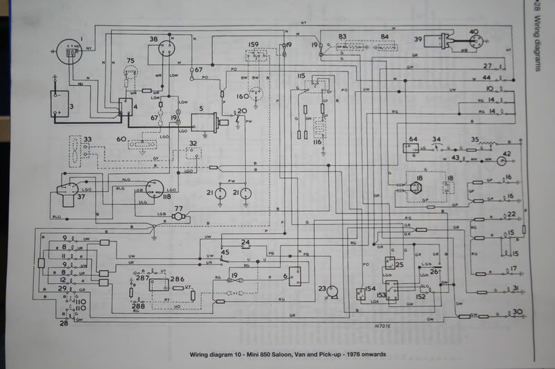
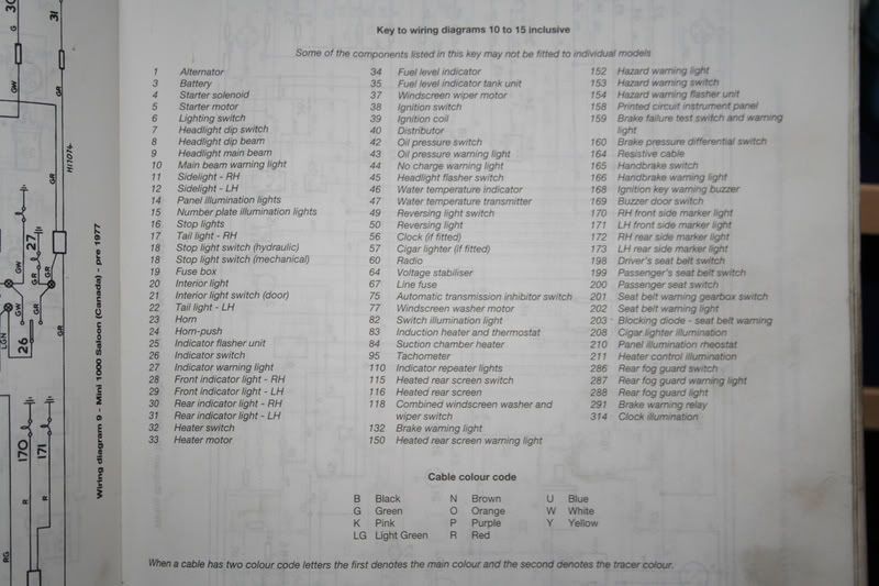
Posted 03 November 2007 - 09:09 PM
I printed out Jammy's schematics and compared them to what I'm more familiar with.
Big_Adam, go back to the first page of this thread and find the link I posted for the MGB wiring schematics. Open it and print out page 32, "Late US Market MGB". Specifically, zoom in on the bottom right corner and use the "print current view" option so you just get a large detail of the hazard circuit on the MGB.
You'll notice that the hazard and turn signal schematic on the page 32 MGB schematic is virtually identical to the one Jammy posted. Here are the differences.
The MGB feeds the hazard flasher with a brown wire. The Mini uses the purple/orange wire. The only difference is the purple/orange wire comes off a brown wire after a fuse. In both cases, the hazard flasher's "B" terminal should have +12V on it at all times as long as the fuse is good.
The MGB schematic puts the turn signal flasher AFTER the hazard light switch, the Mini puts it BEFORE the switch. Functionally... there is NO difference... it can be in either location.
Here's what you need to confirm, with the ignition on, the turn signal flasher should have +12V on its "B" terminal. With ignition on or off, the hazard flasher should have +12V on its "B" terminal.
Zoom in on the MGB schematic. You'll see the hazard switch terminals are numbered. If you've copied Jammy's schematic (turn signal flasher before the hazard switch), there should be a wire from the turn signal flasher's "L" terminal to the hazard switch terminal #8. There should be a light-green/brown wire going from the hazard switch terminal #7 to the turn signal switch on the steering column. If you were to disconnect the wires from the hazard switch there should be continuity between its terminals #7 & #8 when the switch is "OFF". When you turn on the hazard switch there should be NO connection between terminals #7 & #8. In normal mode (hazard switch off) current will pass through the flasher, through the hazard switch, and to the turn signal switch. When the turn signal switch is activated, it will connect power to either the left or right turn signal lamps on the green/white or green/red wires as appropriate.
When the hazard switch is "ON" , the connection between its terminals #7 & #8 will be broken, taking the turn signal flasher out of the picture. However, ALL the remaining four hazard switch terminals will be joined together. What this does is connect the turn signal bulb wires (green/white & green/red) to each other and to the hazard flasher. The third terminal will connect to the hazard flasher's "L" terminal. The fourth switch terminal will be connected to the indicator bulb to show you that your hazards are working.
Go back and make a few voltage measurements, and confirm that you're following either the Mini or MGB schematic. (They are functionally the same so either will work, choose one). Once you've copied the schematics and confirmed that each bulb works on its own, try the hazards and see if you have any problems and report them here. Likewise, turn the hazards off and the ignition on and see if the turn signals are working properly and let us know. Once you've confirmed that you're following one of these schematics and report what the bulbs are doing under each test condition we'll be able to help you sort this out.