So we need to know if you have (contact) breakers then!
How many (thin) wires go from the coil to the distributor?
no i dont have contact breakers
i have two wires from coil to distributor


Speeding Along Now

Posted 01 August 2008 - 09:11 PM
So we need to know if you have (contact) breakers then!
How many (thin) wires go from the coil to the distributor?
..is NOT a girl!

Posted 01 August 2008 - 09:37 PM
Speeding Along Now
Posted 01 August 2008 - 09:41 PM
Let's go back to the basics.
Mark and remove the low-tension wires from the coil.
Place your meter in Ohms mode to measure resistance and place the meter leads across the coil's low tension terminals.
(AGAIN... no wires should be on the low tension coil terminals during this test)
If you measure close to 3 Ohms, you have a standard coil. If you measure 1 to 2 Ohms you have a ballast coil.
Find the wire going to the coil from the ignition switch.
(What color is it? The feed wire to a standard coil is "white", the feed to a ballasted coil is "pink". )
Reconnect ONLY the ignition switch feed wire to the coil V(+) .
Connect a jumper wire between the coil's V(-) terminal and earth.
Switch on the ignition. Measure between coil V(+) and earth. Tell us what voltage you measure.
(A standard ignition will have coil V(+) at 12V, a ballast system will show 6-9 volts on coil V(+). )
If you haven't read the PDF link on points ignition systems please do so.
Edited by marsy, 01 August 2008 - 10:01 PM.
Moved Into The Garage

Posted 02 August 2008 - 11:35 AM
Speeding Along Now
Posted 02 August 2008 - 06:08 PM
At this point I'd suggest you sit down with a wiring diagram for your car, review it, consider your finances, and make some decisions.
If you measured 0.9 Ohm across the coil's low tension terminals (no wires attached) you have a ballast coil. You have not set up wiring for a ballast coil. Frankly... I don't know what damage you may have done hooking a ballast coil up to an electronic ignition module without the ballast resistor/(resistor wire). I don't know how you test the ignition module so others will have to chime in.
As I see it, you can add a ballast resistor (or resistor wire), add a bypass wire from the solenoid, and fit a different distributor with points. OR... you can fit a new standard coil... and probably replace the ignition module on the dizzy you have.
Whichever direction you choose to go you need to make the wiring appear like it does in a Mini's wiring diagram (point or electronic ignition).
Edited by marsy, 02 August 2008 - 06:35 PM.
Moved Into The Garage
Posted 03 August 2008 - 12:45 AM
Speeding Along Now
Posted 03 August 2008 - 08:55 AM
I have not worked on a Mini with electronic ignition so I encourage others to elaborate on, confirm or correct what I say below.
Electronic ignitions do NOT use a ballast coil. My concern is that by running a ballast coil for a short period you may have allowed too much current to pass through the ignition module. This generates excess heat. I don't know if your module still works or not. As I said, I haven't worked on electronic ignition Minis.
Others will have to provide wiring information for the module itself. Every ignition module I've seen on non-Minis requires a source of switched 12V for the module itself. Most have an earth connection through the mounting surface of the module. However, a few German ignitions I've worked on use a dedicated earth wire for the module. Others more familiar with electronic ignition Minis will have to fill in the specifics that apply to your car.
If you use a standard 3-Ohm coil the wiring is straight forward. Go back and look at the figure on page 2 of the PDF I posted the link to on the first page of this thread. You'll see that the coil (+) terminal must be supplied switched +12V power from the ignition switch. The distributor/module has a single wire that goes to coil (-). That's basically it for a standard coil... switched 12V in on coil (+) and a path to earth (through the ignition module) connected to coil (-).
It only gets complicated when you add a ballast resistor and 4-terminal starter solenoid into the equation.
Edited by marsy, 03 August 2008 - 09:22 AM.
..is NOT a girl!
Posted 03 August 2008 - 10:08 AM
Speeding Along Now
Posted 03 August 2008 - 08:30 PM
We need to find out what flavour of electronic ignition you have. Some aftermarket systems aren't too fussy, others - like the factory fitted Lucas kit, use yet another specification of coil. There's still the possibility the coil itself is damaged if its been run at the wrong voltage.
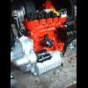
Some piccies of your dizzy with the cap off would help. You could check out: Lucas 59DM4, Lucas 65DM4, Aldon and electronic ignition in general on the web to compare your own. The Minispares site should have piccies of all the likely candidates.
No part number on that coil Unipart GCL... etc?
 dist_005.JPG 523.82K
5 downloads
dist_006.JPG 443.65K
4 downloads
dist_005.JPG 523.82K
5 downloads
dist_006.JPG 443.65K
4 downloads..is NOT a girl!
Posted 03 August 2008 - 08:57 PM
Speeding Along Now
Posted 03 August 2008 - 09:04 PM
Your dizzy is a 65DM4, which is the later of the 2 Lucas ones.
The coil should be Unipart GCL143 - 0.7 to 0.86 ohms
It's not a ballasted system.If you remove the amplifier module (black box) you can check the resistance across the terminals on the dizzy that it plugs in to - 0.95 to 1.5 k ohms is what you want.
Speeding Along Now
Posted 03 August 2008 - 09:12 PM
Your dizzy is a 65DM4, which is the later of the 2 Lucas ones.
The coil should be Unipart GCL143 - 0.7 to 0.86 ohms
It's not a ballasted system.If you remove the amplifier module (black box) you can check the resistance across the terminals on the dizzy that it plugs in to - 0.95 to 1.5 k ohms is what you want.
..is NOT a girl!
Posted 03 August 2008 - 09:16 PM
Speeding Along Now
Posted 03 August 2008 - 09:17 PM
You don't want anything turned on! You'd just unscrew the black box pull it away from the dizzy to expose the terminals to measure across (on the dizzy - not the black box). Personally, I don't think this is the problem if you've had it running - 'leecy ignition tends to work or not at all.
Having had a quick reread, the coil sounds like it's the right one but the voltage sounds a bit low. What voltage have you got at the battery?
Edited by marsy, 03 August 2008 - 09:18 PM.
..is NOT a girl!
Posted 03 August 2008 - 09:31 PM
Edited by Ethel, 03 August 2008 - 09:38 PM.


0 members, 1 guests, 0 anonymous users


