Jump to content


Photo
- - - - -

Wide Ratio Gearbox And 1380 Engine Build


  • Please log in to reply
419 replies to this topic

#16 AndyMiniMad.

AndyMiniMad.

    Up Into Fourth

  • Members
  • PipPipPipPipPipPipPipPipPip
  • 3,290 posts
  • Location: Under The Bonnet.

Posted 17 June 2010 - 09:05 PM

Looks good so far, but you'll be removing the detent sleeve, spring and ball later as if you were actually going to torque the box up, you'll need to lock the gears...

but it's funny seeing how other people do it, like the selector shaft I put in from the other end, not that it makes any difference, may be you're left handed ??

Yep Im a lefty. but I can mess things up equally with both hands. :thumbsup:

#17 evansisgreat

evansisgreat

    One Carb Or Two?

  • Members
  • PipPipPipPipPipPipPip
  • 1,095 posts
  • Local Club: Not yet

Posted 17 June 2010 - 09:26 PM

Ha, nice one mate. Great progress, really inspiring. I'd thinking about following in your foot steps if I wasn't getting rid of the A series.

#18 GraemeC

GraemeC

    Crazy About Mini's

  • TMF+ Member
  • PipPipPipPipPipPipPipPipPipPip
  • 7,315 posts
  • Location: Carnforth

Posted 18 June 2010 - 08:05 AM

Looks good so far, but you'll be removing the detent sleeve, spring and ball later as if you were actually going to torque the box up, you'll need to lock the gears...


I think I'd be taking them out and puting them somewhere safe for now. Unless you have temporarily bolted the diff side cover on they can easily fall out whilst your doing other jobs and never be seen again (well not for a good few weeks/months/years when they'll suddenly turn up miles away from where you are working!!)

Edited by GraemeC, 18 June 2010 - 08:06 AM.


#19 AndyMiniMad.

AndyMiniMad.

    Up Into Fourth

  • Members
  • PipPipPipPipPipPipPipPipPip
  • 3,290 posts
  • Location: Under The Bonnet.

Posted 20 June 2010 - 06:54 PM

Thanks for the advice guys. bits removed and put in a safe place.
Have done a bit more this weekend, these bits are next to put together.
Attached File  018.JPG   1.17MB   13 downloads
I did not replace this bearing but instead took out the plastic insert that holds the balls and gave everything a good clean.
You can see from the picture that the bearing will sit centrally on the shaft.
Now its time to put the gears into the box.
I dont know the correct sequence for doing this so I just placed the gears in making sure they sit properly on the selector forks and then slid a new mainshaft double roller bearing on.
Note i put the retaining clip onto the bearing.
Attached File  020.JPG   1.32MB   17 downloads
Attached File  023.JPG   1.32MB   17 downloads
Also at this stage you can see I have placed the oil pick up cage into the box. Dont bolt it up though as it needs to move out of the way a bit to get the layshaft in later in the build.
Next I placed the roller bearing onto the other end of the mainshaft.
Attached File  024.JPG   1.19MB   10 downloads
Then the 1st motion shaft slides in and over the bearing. I then gently heated the gearbox around the areas where the big bearings go. I did this with a heat gun which normally gets used for paint stripping.
With the box nice and warm I then Gently drifted the bearings in, A small amount on the mainshaft bearing first and then the 1st motion shaft bearing.
The mainshaft bearing should be drifted in all the way to the retaining clip. Once both bearings are in its time to fit the big circlip.
Attached File  025.JPG   1.29MB   9 downloads
The 1st motion shaft drive gear can now be fitted, dont forget the tab washer which locks into place via the two small holes in the gear.
I have not tightened the nut up yet (Just in case ive made a mistake).
Thats it then for now. Hope this is all making sense to you!!!

I have run out of memory space for the pictures now. Can any one tell me how to get more pictures onto this topic. Can I upload to photobucket and get them on that way, or is there a way of getting more than 50MB thread memory

#20 AndrewJ530

AndrewJ530

    Camshaft & Stage Two Head

  • Members
  • PipPipPipPipPipPipPipPip
  • 1,628 posts
  • Location: Middlesbrough

Posted 20 June 2010 - 07:12 PM

Just use photobucket mate. Then you can have as many as you want.

#21 CaptainBland08

CaptainBland08

    Super Mini Mad

  • Members
  • PipPipPipPipPipPip
  • 675 posts

Posted 20 June 2010 - 08:42 PM

i use facebook personally:P

#22 AndyMiniMad.

AndyMiniMad.

    Up Into Fourth

  • Members
  • PipPipPipPipPipPipPipPipPip
  • 3,290 posts
  • Location: Under The Bonnet.

Posted 21 June 2010 - 08:31 PM

Photobucket pictures from now on. hope the quality is ok.
So here is the 1st motion shaft drive gear fitted with the tab washer and nut done up but only hand tight for now.

Posted Image

Next bit is to install the layshaft.

Posted Image

Place the small bearings in the ends.

Posted Image

I placed the spacer washer in the box and slid the shaft in a wee bit to hold it in place while i lined up the layshaft. the end with the slot cut into it goes in first.

Posted Image

Then I pushed the shaft through the gears and fitted the smaller spacer washer to the other end. This is the bit where you will be glad you didnt fit the bolts to the oil pick up cage!

Posted Image

So thats it for today. Its nearly done now. The pile of bits has shrunk a lot. Hope there is nothing left once ive finnished!!

#23 AndrewJ530

AndrewJ530

    Camshaft & Stage Two Head

  • Members
  • PipPipPipPipPipPipPipPip
  • 1,628 posts
  • Location: Middlesbrough

Posted 21 June 2010 - 09:20 PM

It's looking good mate. What's going on top of the box?

#24 AndyMiniMad.

AndyMiniMad.

    Up Into Fourth

  • Members
  • PipPipPipPipPipPipPipPipPip
  • 3,290 posts
  • Location: Under The Bonnet.

Posted 21 June 2010 - 09:40 PM

So far im just building this box for fun. I was not sure I could do a gearbox build.
Im waiting for my other engine block and head to come back from the machinists. 1380, Skimmed 10 thou for higher compression ratio, the head is being ported and the chambers are being polished, head and block mated for a perfect fit, its an MG metro engine so not going to increase the valve size, Fast road cam, hoping for 100bhp,
Once its back keep watching this thread because im going to build it on here, same as the box, with lots of pictures,

Edited by AndyMiniMad., 27 February 2011 - 04:24 PM.


#25 AndyMiniMad.

AndyMiniMad.

    Up Into Fourth

  • Members
  • PipPipPipPipPipPipPipPipPip
  • 3,290 posts
  • Location: Under The Bonnet.

Posted 22 June 2010 - 04:38 PM

So next I slid the retaining plate to the groove on the end of the layshaft and reverse idler gear shaft. It takes a bit of adjustment to get the plate all lined up.
Once thats all lined up I fitted the main shaft roller bearing retainer and shim. Dont forget the locking washer bits.

Posted Image

I then fitted the pick up pipe into the oil cage thingy and fixed in place with the two bolts.
You can see that I have put the final drive gear nut and washer on in the picture. Dont know what final drive im going to use on this box now as ive found out during this build that this box is the wide ratio one which wasnt fitted to that many minis. (got this box from a metro vanden plas). Not from my mini 998 as i first thought.
Just goes to show if you leave things lying around with no lables.

Posted Image

The last bit to fit is the bearing for the iddler gear. I used the paint stripper again to heat the box and then a suitable sized socket to drift it in.

Posted Image

So there you go one gear box all rebuilt.

Will strip and rebuild the diff next and before fitting, I would be gratefull for any advice as to which final drive would work best on this box.

The eagle eyed techy types amongs you will have noticed that the laygear I have fitted in this build is not the wide ratio one.
Please accept my appologies for this, but i had no idea they were different untill i noticed the grooves in the teeth.
I have ordered a correct wide ratio laygear from guessworks and will change it before proceeding with this build thread.

Err... Umm....If You want to know what happend to the original laygear from this box here it is.

Posted Image

Yep its mullered. By ME being stupid, Will not make that mistake again.

Now that I know about this box I was thinking about fitting it back to its original engine (12h17) which has at present got a standard 998 box under it.

So what do you think for the final drive??

Edited by AndyMiniMad., 22 June 2010 - 04:42 PM.


#26 AndyMiniMad.

AndyMiniMad.

    Up Into Fourth

  • Members
  • PipPipPipPipPipPipPipPipPip
  • 3,290 posts
  • Location: Under The Bonnet.

Posted 30 June 2010 - 07:36 PM

Well the bits are here in super fast time from Guessworks and im off to the garage to fit them.
I bought a central oil pick up pipe as well just because ive decided to use this box on the 1380 build.
I removed the laygear, old oil pick up and cage, Then loosely slid in the new pick up pipe.

Posted Image

It fits through the hole in the casing next to the reverse gear idler.
Then its time for the new laygear fitted in the same way as before although the center pick up does get in the way so it took a bit of a shoogle to get it all lined up.

Posted Image

Once it was in and running smoothly I fixed the oil pipe as normal to the back of the box. I did not need to use new gaskets on either side because the old pipe had not been tightened up before removal. The bracket on the pipe is fixed as shown in the picture, I reused one of the old bolts and used a nylock nut.

After advice taken on the forum I have decided on a 3.1-1 final drive, this should give me a really comfortable cruising speed due to the longer 3rd and 4th gears in the wide ratio box, acceleration should still be adaquate due to the 1ts and 2nd ratios being the same as normal, also there will be plenty of torque to pull the longer gears as im building a lightly tuned 1380 to go with this box. (Keep watching)
So here is the 19 tooth gear in place and the big washer fitted, note the tabs have not been bent over yet as i still need to torque the nut to 150.

Posted Image

I have stripped the diff and will post pictures of the build and install when the upgraded pin and gears arrive.
So thats it for now. Hope this is being helpfull to some of you, Let me know if im doing things wrong or maybe there is an easyer way to do some of the stuff in this thread.

#27 AndyMiniMad.

AndyMiniMad.

    Up Into Fourth

  • Members
  • PipPipPipPipPipPipPipPipPip
  • 3,290 posts
  • Location: Under The Bonnet.

Posted 01 July 2010 - 02:27 PM

Hello again. Is any one watching this or is the footy on Ha Ha.
Any way here are the pictures of the diff strip. Even if it is only me.
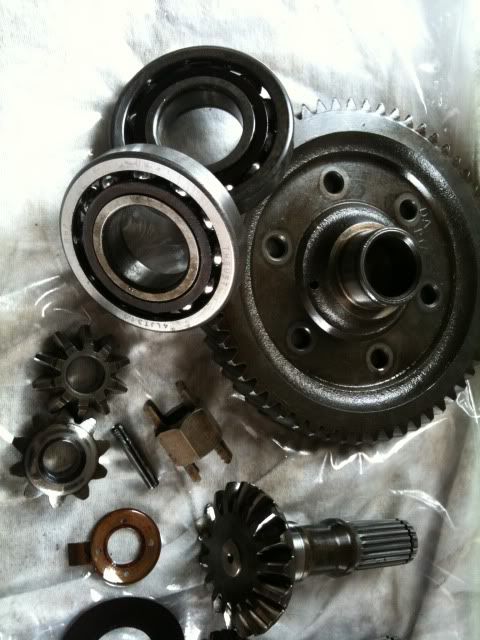
First I used the bearing pullers thinking the bearing would just pop off in one piece. Got a bit of a shock when the outer race came off and left all the balls and bits still on the shaft,

Posted Image

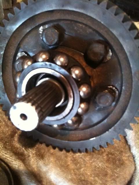
So i pulled off the ball cage by hand.

Posted Image

And then used the pullers again to remove the inner race.

Posted Image

Now I thought id broken the bearings and was about to order new when guessworks told me thats what happens with these bearings and not to worry because they go back together with a sharp tap of the persuader.

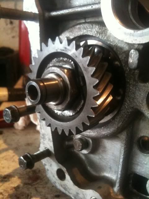
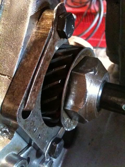
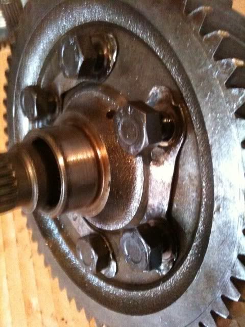
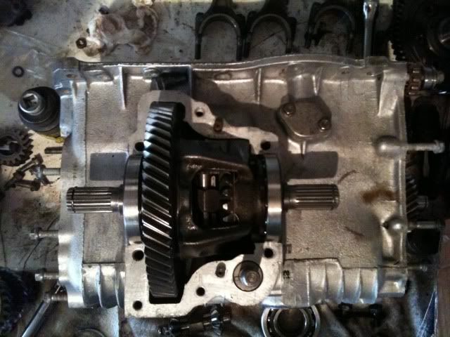
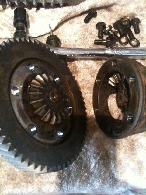
Next job was to get the crown wheel off and let me tell you those bolts are torqued to "F" tight. Clamped the cog in the vice and got the long bar on to it.
You can see from the picture that I had already opened the tab washers.

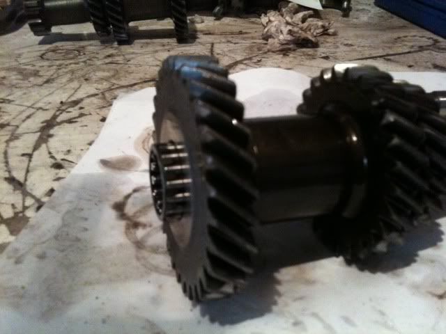
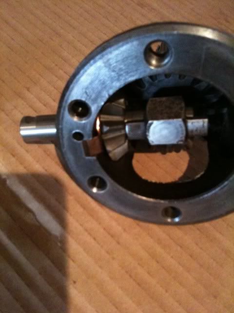
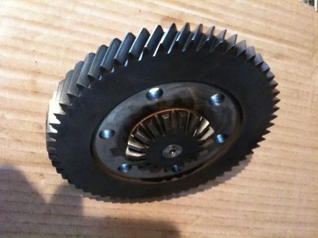
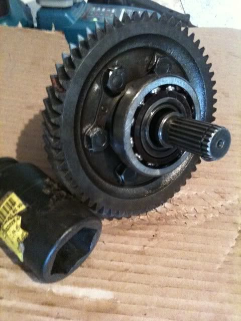
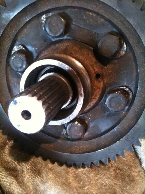
Here it is with the crown wheel off.

Posted Image

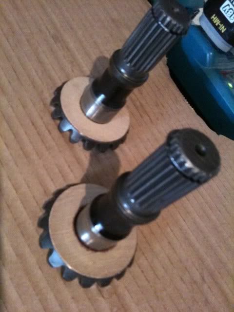
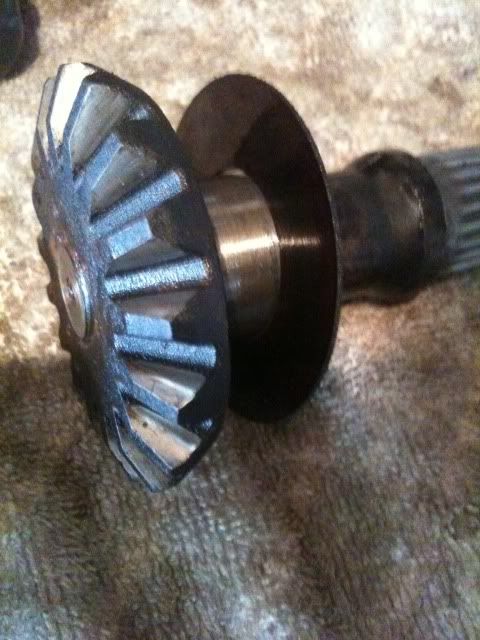
The long spindle cog thing (sorry dont know its name) Will now pull out of the crown wheel, but dont loose the big plasticy washer, you might need it when rebuilding, Ive heard the new ones that come in the rebuild kits are a tiny bit thicker.

Posted Image

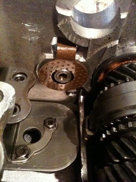
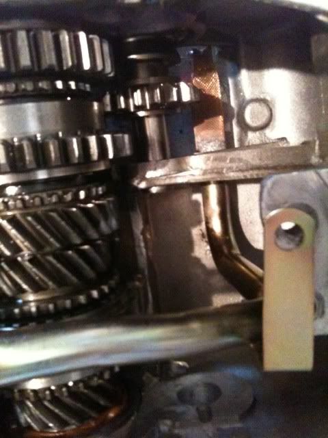
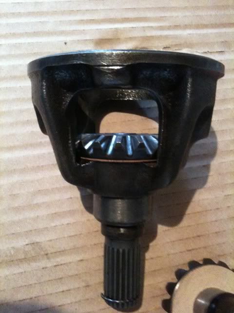
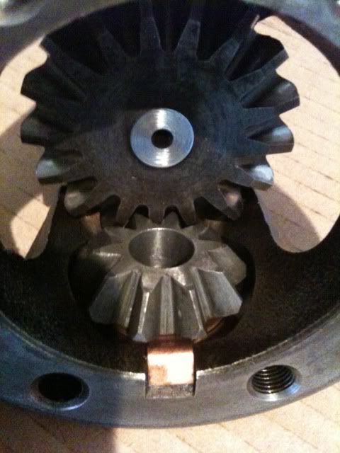
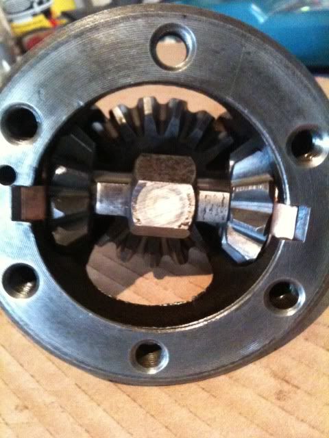
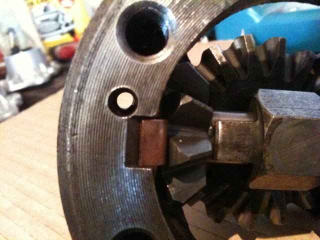
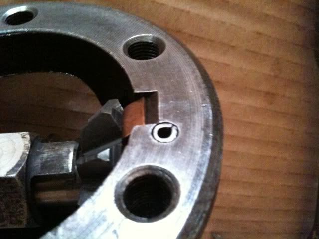
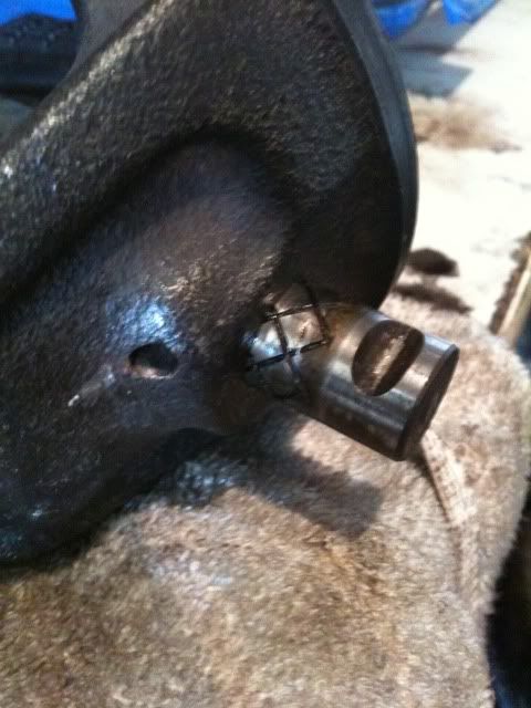
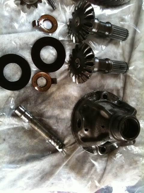
This next picture is the roll pin which holds the diff pin in the cage, This is also in very tight but with a few spirited blows with the hammer it started to come out.

Posted Image

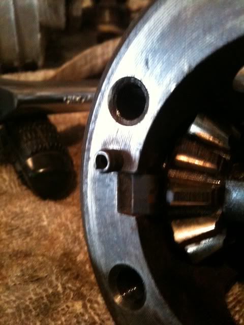
Once you get it out you can tap out the diff pin you can see the groove in the diff pin where the roll pin sits.

Posted Image

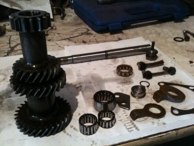
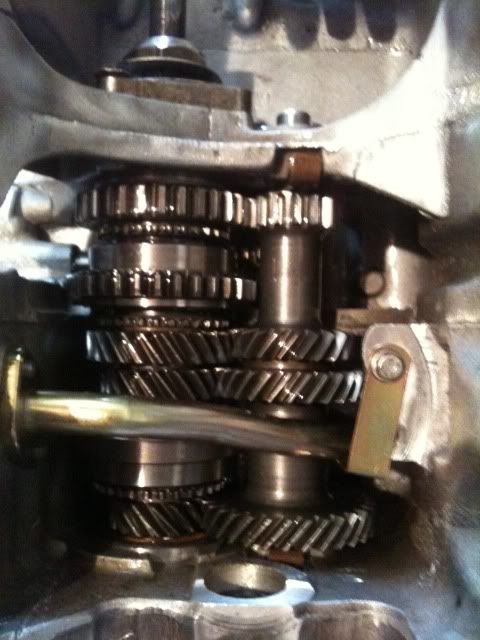
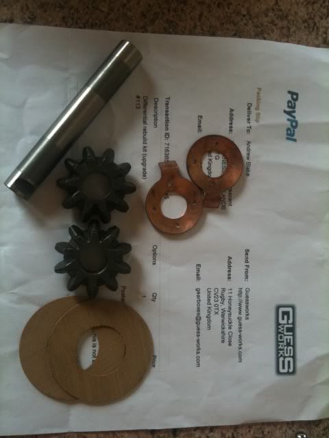
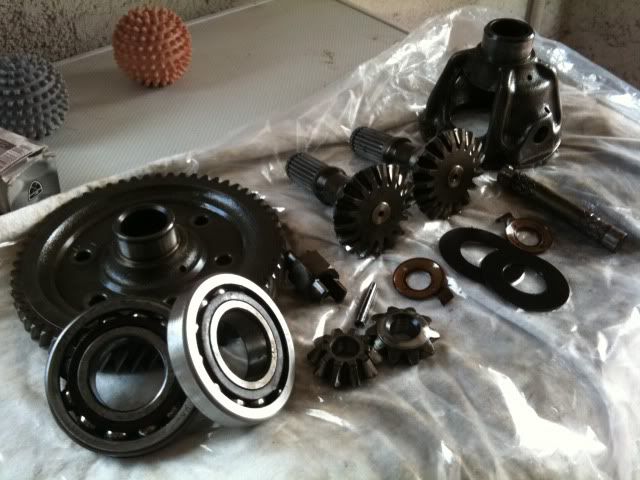
With the diff pin out all the other bits just kinda fall out, the small cogs and copper looking shells. and thats it stripped. All the bits.

Posted Image

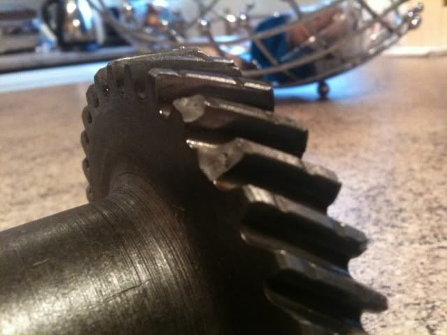
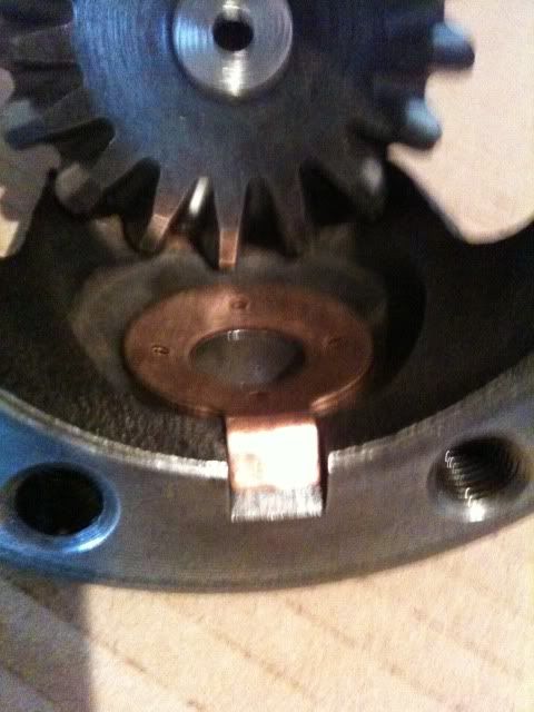
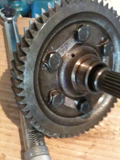
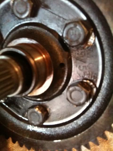
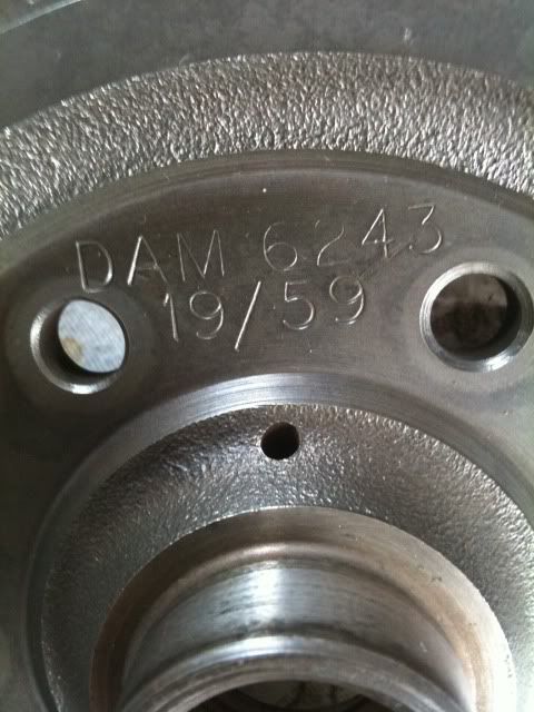
This is the stamp on the crown wheel which lets you know what your final drive ratio is, crown wheel 59 teeth, drive cog in box 19 teeth. 59 divided by 19 =

3.105. So the final drive ratio is 3.1-1 on this box.

Posted Image

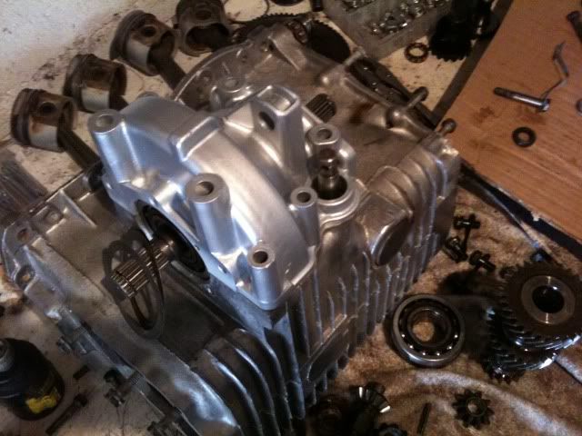
Now a quick swim in the degreaser a light coating of oil and its time for the photo shoot.

Posted Image

Posted Image

The uprated diff pin kit is on its way from Guessworks so i will put it all back togeher when it arrives.

Byeeee!!!
Edit.
A quick clarification, When I say "degreaser" What I really mean is an old buscuit tin filled with "GUNK" and a paint brush. ""It does the job people""
Edit Edit.
The calculation for the final drive ratio above is not something I just knew about, I found out by asking in the technical section and thought I would share. Sorry If I sounded like a bit of a "know it all". because I really dont.

Edited by AndyMiniMad., 27 February 2011 - 04:40 PM.


#28 Guess-Works.com

Guess-Works.com

    Gearbox Guru

  • Traders
  • PipPipPipPipPipPipPipPipPipPipPip
  • 19,838 posts
  • Local Club: Rugby Classic Mini Owners Club

Posted 02 July 2010 - 01:25 AM

Diff kit should be with you tomorrow, and you should not have an trouble with the fibre's, it was about 2 years ago that the batch hit the circuit which were about 10 thou' too thick, but since then the std BTA101's are back. Don't forget the spring rings for the ends of the pot joints, I see from the photo's that they are missing and it's a lot easier to put them on when the diff is in bits...

The CW to diff cage bolts are not that tight, and to tighten up, if you have a deep enough vice, grip the diff by the cage in a vertical position ( ie so the crownwheel is in the horizontal plane ), gripping it by the crownwheel can chip the teeth, as with all gears and as you've found out already, they are hard but rather brittle.

#29 AndyMiniMad.

AndyMiniMad.

    Up Into Fourth

  • Members
  • PipPipPipPipPipPipPipPipPip
  • 3,290 posts
  • Location: Under The Bonnet.

Posted 02 July 2010 - 08:32 AM

Thanks Guesswoks, Another great piece of advice. The spring rings are now back on.
Cheers

Andy

#30 AndyMiniMad.

AndyMiniMad.

    Up Into Fourth

  • Members
  • PipPipPipPipPipPipPipPipPip
  • 3,290 posts
  • Location: Under The Bonnet.

Posted 02 July 2010 - 02:04 PM

As primised the upgraded diff kit arrived today. Yahoooo...Now I know I should not get excited about this but im in the north of scotland and next day delivery is rare..

Posted Image

And so to the garage I go.........Right then I started by plonking the new fibre washers over the pinion gear shaft things. gonna call them "Bob" because I have no idea what the real name is.

Posted Image

Note I have fitted the spring clips as instructed. Next I put "Bob" in his cage.

Posted Image

Then I placed the new copper looking washer thing in the cage and then the new planet gear on top. Is this the planet gear or is it "Bob"?

Posted Image

Posted Image

Next up was to slide the new diff pin in and place the center bit that seperates the two Planet gears on the pin as it slides through. Make sure you are keeping the slot in the end of the diff pin in possition for the roll pin to fit. Also note the possition of the middle bit. The fork bits that stick out should face "bob"

Posted Image

Then the last planet gear and copper looking washer go on the other end and the diff pin can be pushed all the way in.

Posted Image

At this stage you will realise why it was important to keep the slot in the diff pinn lined up because if you cant see through this hole you wont be able to put the roll pin in.

Posted Image

Posted Image

Make sure it sits flush or even slightly inside the hole. Now I put the other "Bob" into the crown wheel.

Posted Image

And bolted the crown wheel back onto the cage. Dont forget the bits that go behind the bolts.

Posted Image

Then I torqued them up to 56 ntm and knocked over the tabs. I dont know the correct torque for these bolts so I just guessed at 56 being enough.

Posted Image

The Diff bearings went on next with the help of my deep ball joint socket and the hammer.

Posted Image

And there you have it, 1 rebuilt and upgraded diff.

I have placed it on the gear box for a nice picture, and then put the diff housing over to keep the dirt off for now.

Posted Image

Posted Image

Yes I did paint the diff housing!!! I know Im a sad old git!!!

Next will be the gaskets and time to get the shims sorted, I kept the old ones nice and safe so I am just going to bung them back in and try it. But I have a sellection of shims from two other boxes so im fairly confident I can get it sorted.

See ya!

Edited by AndyMiniMad., 27 February 2011 - 04:46 PM.


0 user(s) are reading this topic

0 members, 0 guests, 0 anonymous users