Hi;
Couple of posts already about this Mini in the forum but I thought I'd start a project thread.
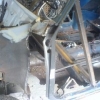
My son bought a Mini with the intention of getting it MOTs and driving it. After we picked it up there was a lot more rust than first thought. We managed to get a load of welding done via a work colleague (about 16 hours worth) which include replacing the Drivers Side A Panel and part of the Flitch. To keep the costs down the rest was just patches (some big ones) to get it through an MOT.
Anyway its now back in my garage and needs more welding.
I am now the proud owner of a second hand (used once) Clarke 160EN Turbo MIG welder and I am up for tackling the job myself but I have never welded before.
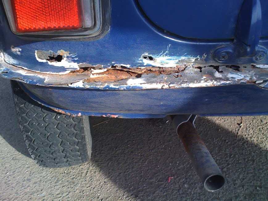
The areas that still need doing are a couple of small holes in the floor (easy or so I thought until I started digging around) and the boot. The boot area is pretty bad and will eventually need a full repair (floor edges and boot hinge area above the bumper (full length)) and the rear arches are looking pretty ropey.
Anyway so far we have replaced the Drivers side A Panel, Door Post Stiffener, Drivers Side Flitch and carried out some repairs to the Sills and floor.
First up a couple of photos showing some of the work that needed doing:
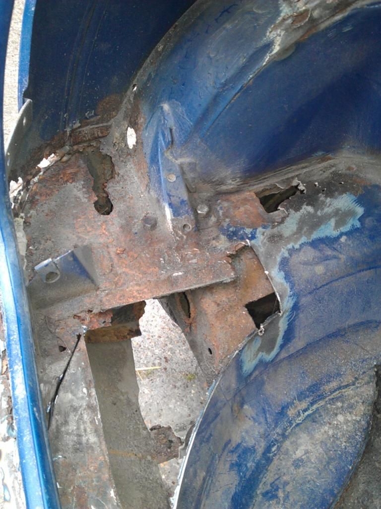
The worst area at first glance was the drivers side A Panel.
The rear end had been hidden away under many layers of filler and once remove OMG!!!
A few bubbles of paint but once removed the real damage could be seen.
More in a mo


1982 Austin Mini - Project Who?
Started by
JonnyAlpha
, Mar 28 2011 04:20 PM
852 replies to this topic
#1

JonnyAlpha
-
- Members
-

- 2,748 posts
Up Into Fourth
- Location: North Devon
- Local Club: Exmoor Minis
Posted 28 March 2011 - 04:20 PM
#2
JonnyAlpha
-
- Members
-
- 2,748 posts
Up Into Fourth
- Location: North Devon
- Local Club: Exmoor Minis
Posted 28 March 2011 - 04:47 PM
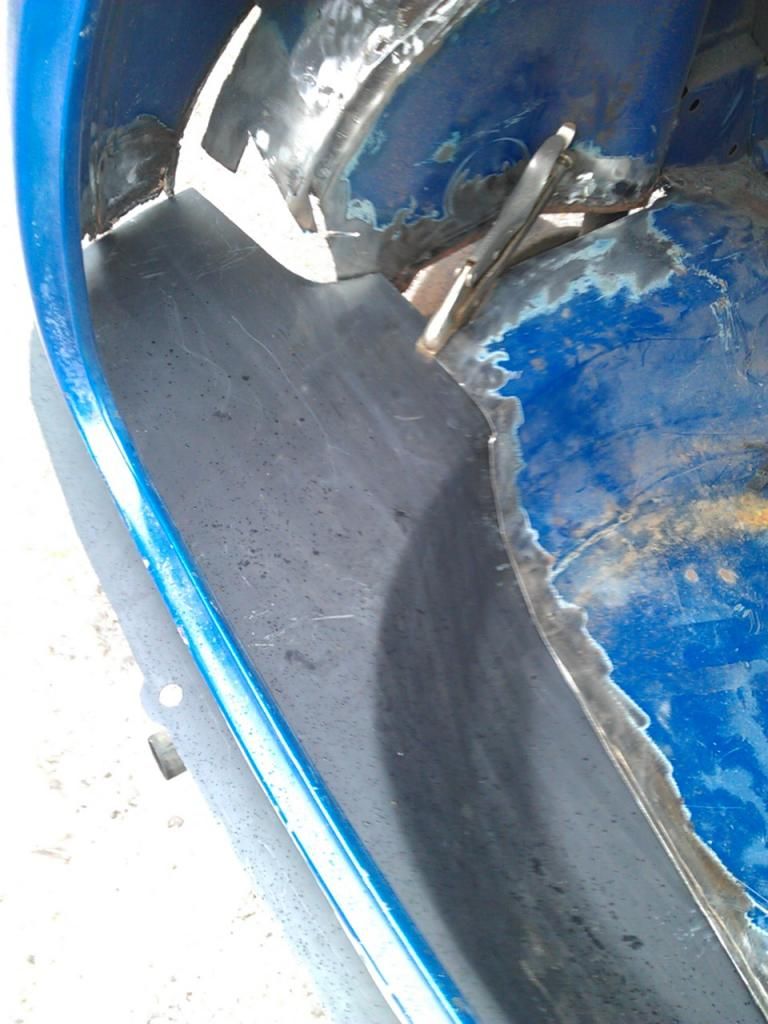
First job was to replace the A Panel and I think the hardest part was working out which parts we needed. We ended up getting an A Panel (of course) but because of the damage to the door post we also bought an A Post Stiffener and an a surround repair.
Heres the A panel and worst parts of the door post surround getting removed, we didn't go so far as removing the whole door post as this would have involved building a support to prevent the body warping.
 APanelRemoveal.JPG 31.34K
126 downloads
APanelRemoveal.JPG 31.34K
126 downloads
Next we removed the worst parts of the Fitch Panel and then fitted the door post stiffener and surround and the Fitch Panel which was then welded in place.
FitchRepairPost.JPG 22.74K
139 downloads
Next up was the A Panel which was spot welded in place, the trick learnt elsewhere on this site was to drill a couple of holes and bolt it in place as well as using a couple of mole clamps to prevent the panel moving.
APanelRepair.JPG 28.85K
125 downloads
Of course another problem was that due to the state of the A Panel all the door hinge bolts were really badly corroded and had to be cut of so we needed to replace then. The hardest part was drilling out the bolts from the hinges, these were real hard and we went through 2 cobalt drills.
Once removed we cut down some 13mm threaded bar, held them in place with 13mm nuts and spot welded them in place. the nuts at the top were not welded as they had to be removed they were just there to hold the threaded bar in place whilst the underside nuts were welded.
DoorBolts.JPG 822.87K
169 downloads
Once the shims were fitted and a couple of extra washers on the top hinge the door fitted lovely and when closed it sounded just like a GOLF
Heres the A panel and worst parts of the door post surround getting removed, we didn't go so far as removing the whole door post as this would have involved building a support to prevent the body warping.
APanelRemoveal.JPG 31.34K
126 downloadsNext we removed the worst parts of the Fitch Panel and then fitted the door post stiffener and surround and the Fitch Panel which was then welded in place.
FitchRepairPost.JPG 22.74K
139 downloadsNext up was the A Panel which was spot welded in place, the trick learnt elsewhere on this site was to drill a couple of holes and bolt it in place as well as using a couple of mole clamps to prevent the panel moving.
APanelRepair.JPG 28.85K
125 downloads Of course another problem was that due to the state of the A Panel all the door hinge bolts were really badly corroded and had to be cut of so we needed to replace then. The hardest part was drilling out the bolts from the hinges, these were real hard and we went through 2 cobalt drills.
Once removed we cut down some 13mm threaded bar, held them in place with 13mm nuts and spot welded them in place. the nuts at the top were not welded as they had to be removed they were just there to hold the threaded bar in place whilst the underside nuts were welded.
DoorBolts.JPG 822.87K
169 downloadsOnce the shims were fitted and a couple of extra washers on the top hinge the door fitted lovely and when closed it sounded just like a GOLF
#3
LewisEdge
-

- Noobies
-
- 36 posts
On The Road
Posted 28 March 2011 - 06:10 PM
Nice work so far! Keep it up!
#4
daveeeeee
-

- Members
-
- 684 posts
Super Mini Mad
Posted 28 March 2011 - 06:33 PM
Those hinges really are hard! Good job though
#5
minimuk
-
- Members
-
- 1,946 posts
Camshaft & Stage Two Head
- Location: Midlands
Posted 28 March 2011 - 08:40 PM
Hi,..that is great idea/remedy and so obvious those hinge repairs  , will never buy "new" ones again!!
, will never buy "new" ones again!!
#6
malcs_miniturbo
-
- Members
-
- 602 posts
Super Mini Mad
- Location: swindon
Posted 28 March 2011 - 08:43 PM
nice work mate keep it up
#7
JonnyAlpha
-
- Members
-
- 2,748 posts
Up Into Fourth
- Location: North Devon
- Local Club: Exmoor Minis
Posted 28 March 2011 - 10:19 PM
Thanks guys, but what happened to the pics in my first post they haven't showed up???
#8
JonnyAlpha
-
- Members
-
- 2,748 posts
Up Into Fourth
- Location: North Devon
- Local Club: Exmoor Minis
Posted 29 March 2011 - 08:38 PM
Ok here's the latest repairs.
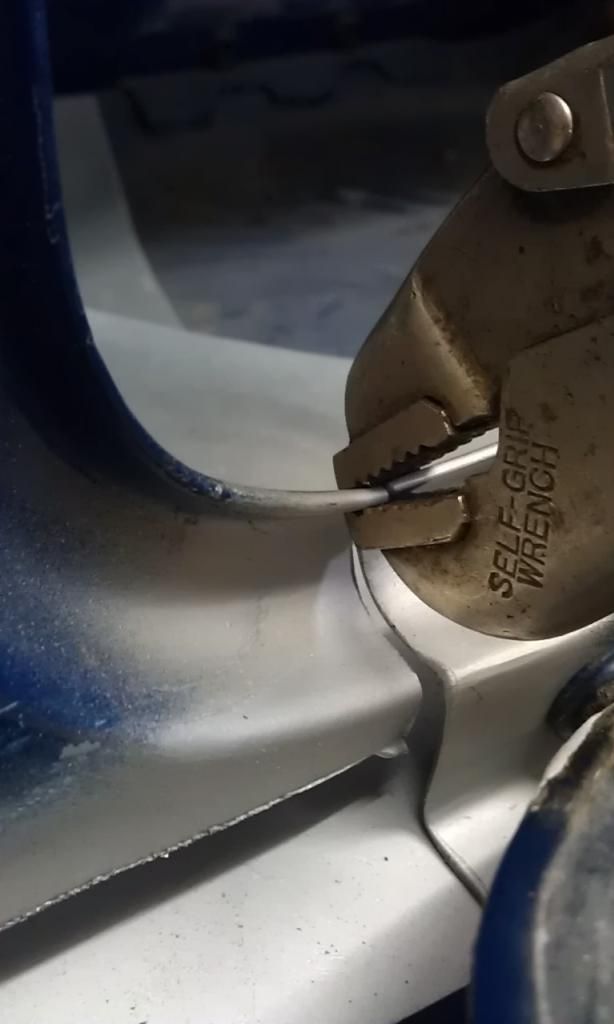
Now that I got my own welder I thought I'e start on a couple of small holes in the rear passenger floor. I mean these holes were no bigger than 2 - 3mm just where the floor pan meets the cross member. But as with all things Mini once the paint was removed more damage was revealed, this ended up in a piece about 150mm x 200mm being cut away (sorry didn't measure it)!!
First I tried a small repair but my welding (the first non test on this Mini) didn't go too well, this was a butt weld, one side welded fine but the other kept blowing through.
FIrstFloorWeldBlowThrough.jpg 24.14K
116 downloads
FIrstFloorWeldGround.jpg 85.27K
79 downloads
Before continuing I tried a couple more tests and realized my technique was to blame. I was going to fast, not concentrating, not getting in a position where I could see exactly what I was doing and not holding the Torch Shroud close enough to the area being welded.
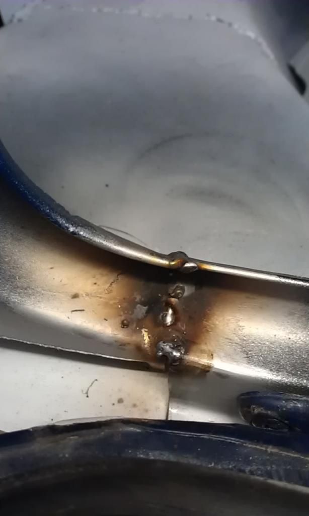
Anyway I contemplated cutting this first repair out and starting again but after a successful test (a lap weld and a butt weld) I had a go at filling in the gaps and was successful.
FirstWeldRepaired.jpg 39.08K
88 downloads
So then I ground it down and as I won't be touching it for a couple of weeks (got to go away) I sprayed it with Acid Etch Primer, can this be welded without removing?
FirstMiniWeld.jpg 28.71K
77 downloads
MiniFirstRepairSprayed.jpg 13.55K
45 downloads
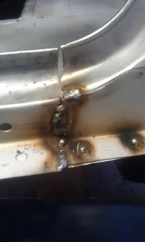
I then decided to make a repair piece to cover the whole affected area and my first thought is to weld it on the underside, but this means it wont be flush inside but as it will be under the carpet it wont be seen or should I try to cut it to size and But Weld it in place?
HomeMadeFloorRepair.jpg 17.92K
48 downloads
More to come later.
Now that I got my own welder I thought I'e start on a couple of small holes in the rear passenger floor. I mean these holes were no bigger than 2 - 3mm just where the floor pan meets the cross member. But as with all things Mini once the paint was removed more damage was revealed, this ended up in a piece about 150mm x 200mm being cut away (sorry didn't measure it)!!
First I tried a small repair but my welding (the first non test on this Mini) didn't go too well, this was a butt weld, one side welded fine but the other kept blowing through.
FIrstFloorWeldBlowThrough.jpg 24.14K
116 downloads
FIrstFloorWeldGround.jpg 85.27K
79 downloadsBefore continuing I tried a couple more tests and realized my technique was to blame. I was going to fast, not concentrating, not getting in a position where I could see exactly what I was doing and not holding the Torch Shroud close enough to the area being welded.
Anyway I contemplated cutting this first repair out and starting again but after a successful test (a lap weld and a butt weld) I had a go at filling in the gaps and was successful.
FirstWeldRepaired.jpg 39.08K
88 downloadsSo then I ground it down and as I won't be touching it for a couple of weeks (got to go away) I sprayed it with Acid Etch Primer, can this be welded without removing?
FirstMiniWeld.jpg 28.71K
77 downloads
MiniFirstRepairSprayed.jpg 13.55K
45 downloadsI then decided to make a repair piece to cover the whole affected area and my first thought is to weld it on the underside, but this means it wont be flush inside but as it will be under the carpet it wont be seen or should I try to cut it to size and But Weld it in place?
HomeMadeFloorRepair.jpg 17.92K
48 downloadsMore to come later.
Edited by JonnyAlpha, 30 March 2011 - 07:49 PM.
#9
JonnyAlpha
-
- Members
-
- 2,748 posts
Up Into Fourth
- Location: North Devon
- Local Club: Exmoor Minis
Posted 30 August 2011 - 06:12 PM
Long time since Iv'e updated this thread, mainly because Iv'e had no cash and I have been saving like crazy to get on with the next phase. Anyway Iv'e been scrimping and saving and telling the missus "Of course I spent the whole £40 on petrol"
Anyway after months of saving I have just ordered:
Somerford: £65.40 (Includes £15.00 delivery charge)
14A9535P L/H Sill
14A9534P R/H Sill
REPAN059 Front L/H Floor Pan
CZH3058P Boot Hinge Repair Centre Section
REPAN060 Rear Panel Below Rear Light R/H (REPAN061 L/H currently out of stock)
Minispares: £78.04 (Includes £7.50 delivery charge)
MS54 Boot Floor Panel Repair Section (The one that runs the full length of the boot)
MS43 Rear Subframe Bolts and Bushes Pack 1979 On
MS51R MS51L Subframe Mounting Rear Panel (Heelboard Repair Sections)
Toolstation: £13.58 (Free delivery)
Twisted Knot Wheel - For Angle Grinder
Twisted Knot Cup - For Angle Grinder
Hard Cap Knee Pads (At long last my poor old knees could do with a rest)
Adams Gas: (£93.19 Includes £50 deposit and £10 delivery charge )
Bottle of 5% CO2 Argon Mix from Adams Gas
Bought a few other bits and pieces a while ago such as 60Watt Worklamp, LED light for my welding torch, cutting and grinding discs.
I am off on a late Bank Holiday Long Weekend 01 Sep 11 - 04 Sep 11 inclusive so will have at least 3 days hard graft so I'll take some photo's along the way and post back the results, hopefully all of my research on this site and others will have paid off.
Wish me luck
#10
JonnyAlpha
-
- Members
-
- 2,748 posts
Up Into Fourth
- Location: North Devon
- Local Club: Exmoor Minis
Posted 10 July 2013 - 07:53 PM
Well a forced move abroad has certainly put a damper on this project and its been garaged for a year or so but I have been on a four week break and managed to make some progress.
I did some repairs late in 2011 and never posted them but did keep a diary which I have updated over the last few days and will upload it in stages along with pics, I also may have another day or so to add by the weekend and then its back in the garage (storage) for another six months then hopefully back on it to the end!!!
P.S. I have also change the name of the project WHO? The Mini will be themed on - wait for it and I know its geeky Dr Who, don't tell me there's one already!!!
Sometime Late 2011
Well three weekends of hard graft and I’ve made a little progress.
I made a decision to start work on the boot floor and rear end as it was probably in need of the most attention, I scoured the internet and found a few posts with helpful information on how to go about the work.
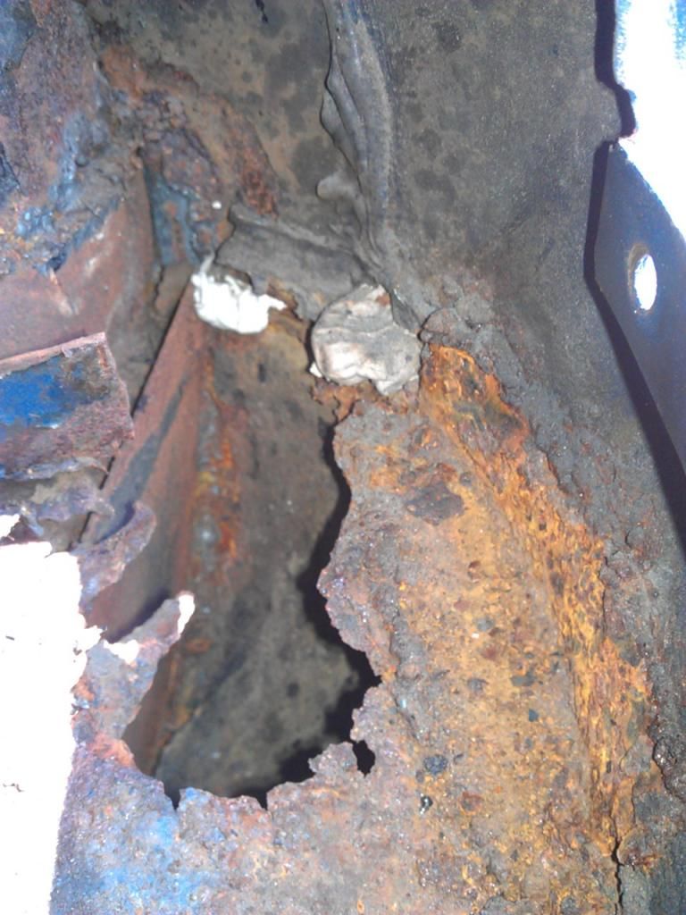
Heres a pic of the LH corner and shows an all too common sight under the filler:
First up I had to remove the fuel tank but as it still has some fuel in I had to be careful. First up I removed the fuel cap otherwise it won't slip through the hole in the body panel.
I disconnected the fuel tank securing strap and manoeuvred the tank so that it was on its side and the fuel line jubilee clip was visible.
I disconnected the fuel line and plugged it with a bolt to prevent any muck from getting in the fuel line.
I also covered the outlet in the tank with polythene and a rubber band. I also found that there was an overflow that also needs plugging using the same method.
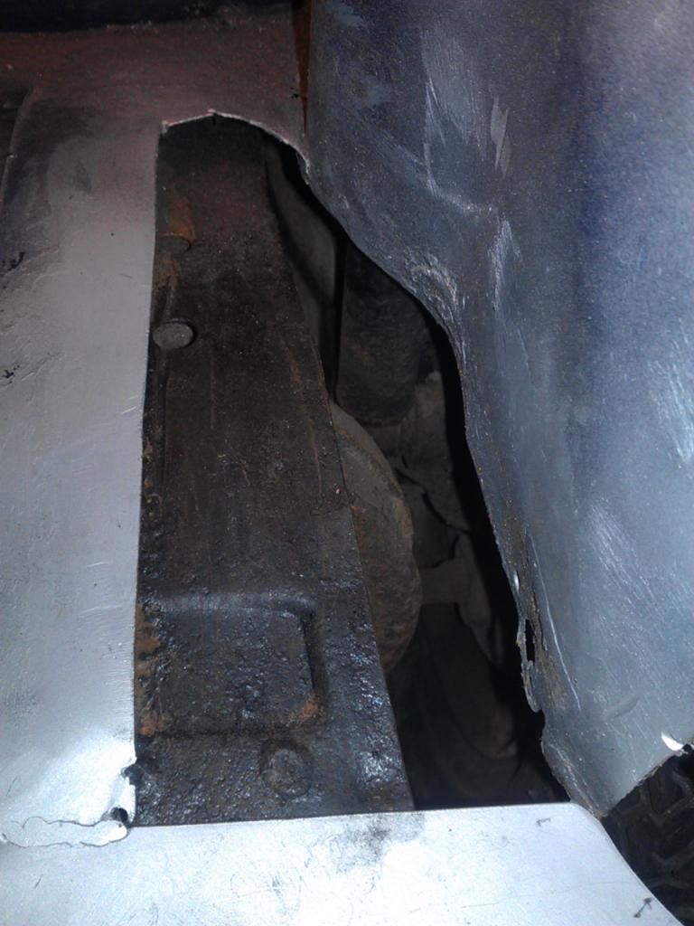
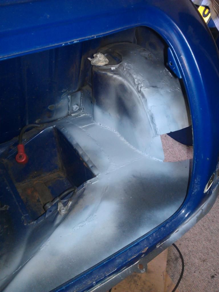
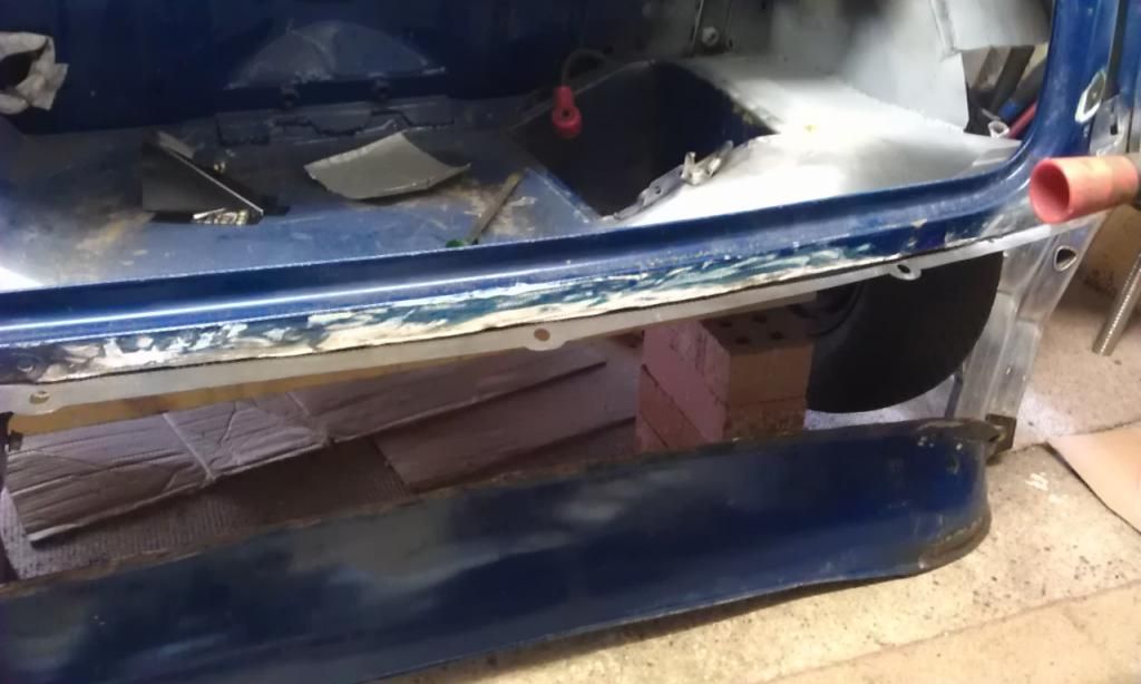
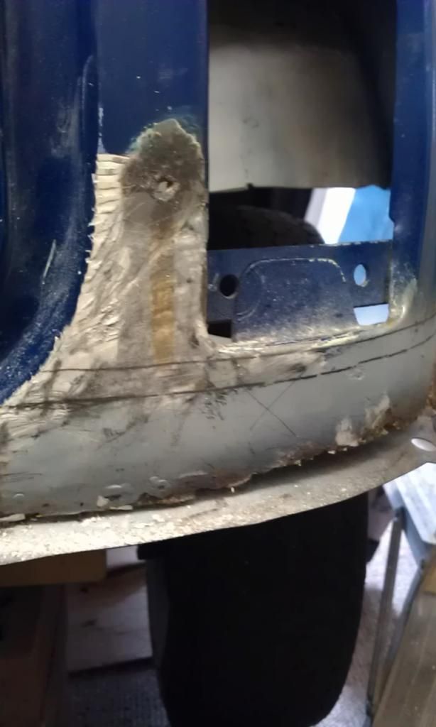
With the fuel tank out of the way I could see the extent of the rot behind mainly in the rear corners and the rear lower part of the arches between the arches and the rear lights.
Here's a pic showing the type of rot in the corners:
Virtually the whole length of the rear end under the rear lights and below the boot hinge panel was rotten and had been filled with filler so I set about removing all of the filler plugging the gap between the boot hinge panel, boot floor and the rear valance. (What a mess that made).
Once that was gone it didn’t take much to remove the rear valance (it nearly fell off), the valance in itself is in pretty good nick, its obviously a later edition and will be salvaged to be re-used.
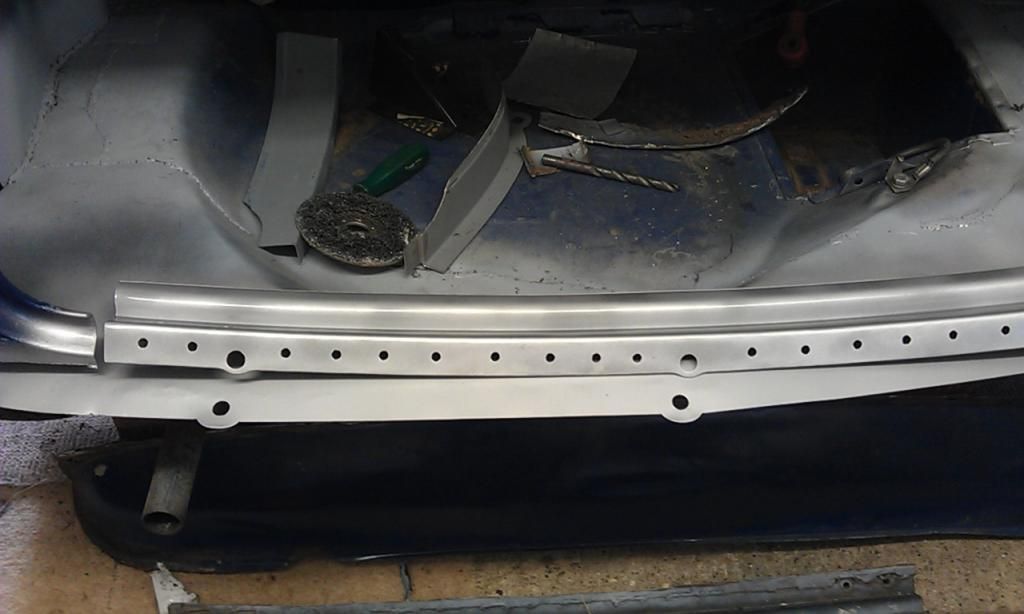
Once the rear valance was out it was time to remove the most of the rear floor well at least enough to fit the rear floor repair panel.
As I had (foolishly for a beginner) decided to attempt to butt weld the repair panel to the existing floor it took a lot of trimming and grinding of both the rear floor area that had been removed and the repair panel to get them to line up nicely, amazingly with a lot of patience I managed it. Once they where held in place I tack welded.
Here's the start of the boot floor removal:
And here's a trial fit of the repair panel after cutting out the rest of the rot, panel is held in place with a pair of Mole Grips:
Looks better already!!!
As seen the rear corners and areas of the floor and rear arches where the Rear Sub Frame mounts are welded were also pretty bad so I cut them out. I now have to order 2 x Rear Sub Frame Support Brackets and will have try an manufacture some pieces to patch up the rear arches whilst ensuring that the Rear Sub Frame Mounts fit in place.
After cutting out the rotten areas of the rear floor along the length of the either rear arch I manufactured some home made repair pieces and again with a lot of patience I butt welded them in place. Lap welding would have been a lot easier and probably stronger but I did not want the repair to be visible but in hind sight I maybe should have cut the repair pieces slightly larger and joggled[1] the edges I am determined to do this right??
Here are some pics of the process:
Here's the hole:
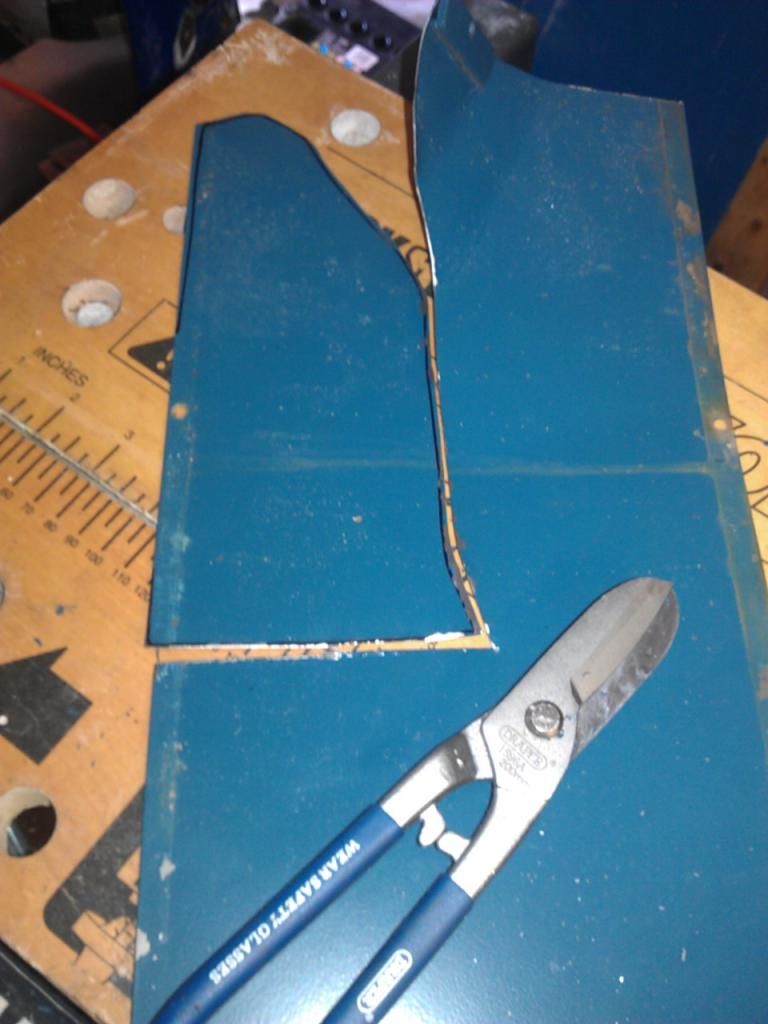
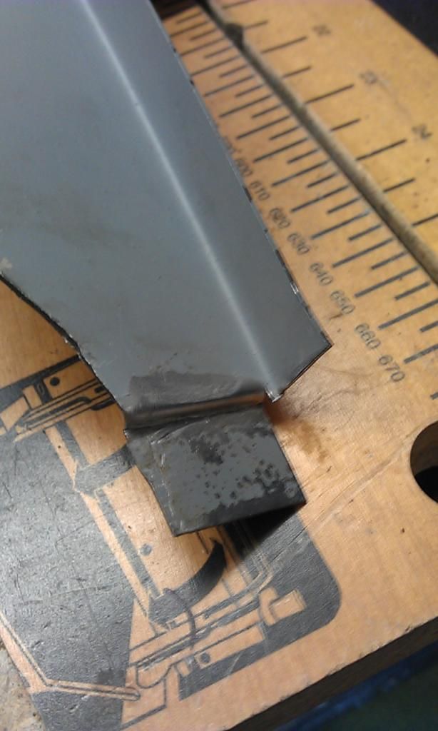
R/H Repair piece being cut out of some mild steel salvaged from a steel cabinet  also showing my new DRAPER Tin Snips.
And here it is partially welded in place: (Sorry about the welding - it does get better)
And as I was having to leave it for a while I sprayed it with U-POL Zinc Primer to protect it.
My welding does get better trust me, the welds are a little cold but some areas are OK and others are rushed. What I have found to improve my welding is confidence, ensuring that you can see what you are doing and having good control of the torch, not to mention the basics such as clean metal, correct power, wire and gas settings!!
One of the problems that I faced was the rear wheel arches, they could do with being replaced but I cannot afford it. Looks like I’ll just have to patch them up as best I can.
Here's a couple of pics of the first patchwork!!
These were done before the boot floor was welded in place. In the pic is the original Earth Clamp that came with my second hand Clarke 160EN Mig, I have now replaced it with a much better 200 Amp jobber and I believe it has helped improve my welding.
All in all the repair so far has gone reasonably well the welding in places leaves a lot to be desired and appears to be on the cool (not good) side!! Probably because I am determined to butt weld, which is not the easiest of welds to complete and with a torch that is too hot cause holes to be blown in the area being welded, hence my tendency to weld too cool. Practice Practice Practice!!!
[1] Joggling is a method of creating a lip along the edge of a repair panel that will fit neatly over or under overlapping the part being repaired, thus enabling the joint to be lap welded in two places.
Edited by JonnyAlpha, 13 July 2013 - 08:47 PM.
#11
JonnyAlpha
-
- Members
-
- 2,748 posts
Up Into Fourth
- Location: North Devon
- Local Club: Exmoor Minis
Posted 11 July 2013 - 09:52 PM
21 June 13
Been away for a year or so but now have a four week break to do a bit of work on the Mini, other commitments as well but will manage at least a week to work on the project.
Remaining Rear End Tasks are:
- Fabricate and fit Rear Arch repair pieces, try out various methods.
- Fit sub frame support bracket.
- Fit repair pieces under rear lights and rear boot hinge panel.
- Drill Through Rear Sub Frame into new floor repair panel.
- Remove rear Sub Frame.
- Fit Rear Sub Frame rear panel support repair panels.
- Weld underside of floor repair panel to ensure strength.
- Clean up and fit fuel tank securing strap support bracket.
- Grind down welds.
- Seam seal edges.
- Prime.
Decided to start with bullet 3 above, notes on what I need to do are:
Under Rear Lights and Boot Hinge Panel Repair
To cut cost I opted to buy the rear end repair panels in three pieces 2 x Rear Light lower panels and the Boot Hinge repair panel. This will present its own challenges when lining it up and welding in place as when I cut out the remaining rot the remaining upper section could be unstable?
To assist in lining up the centre section one idea would be to bolt the boot hinges and boot to the boot hinge repair centre section and close the boot. With this in place as long as the boot opens and closes OK the boot hinge repair panel can be tack welded in place.
Research from the Miniforums suggest that where this repair panel meets the boot floor it should be plug welded so before fitting it remember to drill some holes in the panel.
Here's a pic of some of the damage to be repaired:
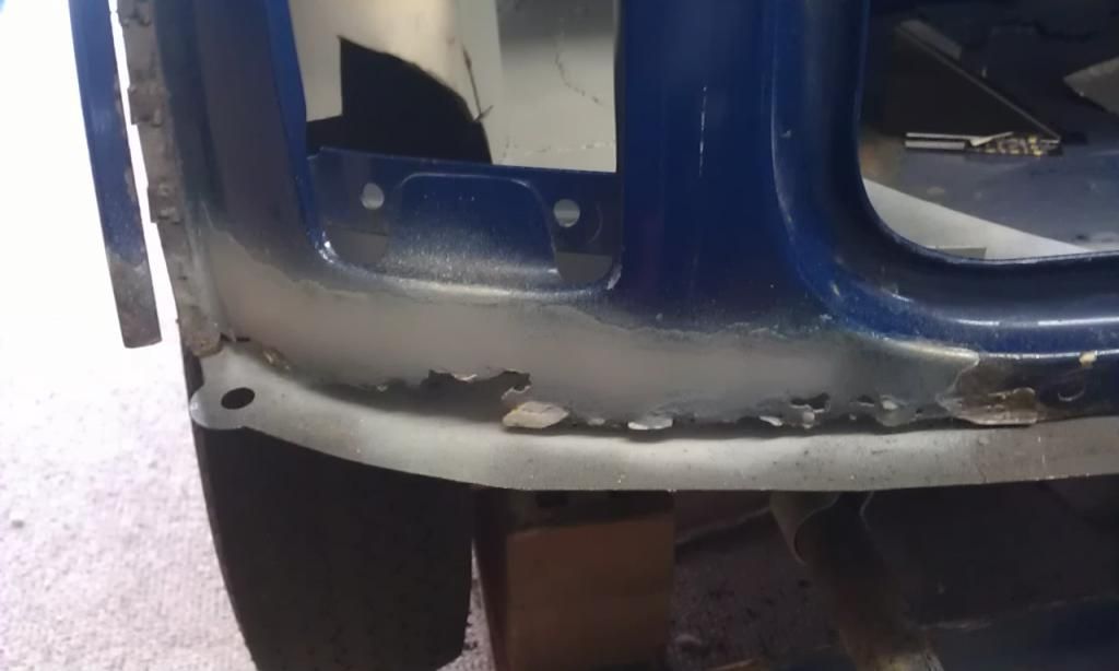
Its like this the entire back end:
My planned steps for both the above repairs are as follows:
Under Rear Light Repair Panel Tasks
These repair panels appear to have a joggled edge enabling them to be lap welded in place.
- Test fit repair panel
- Mark around repair panel onto existing damaged area taking into account joggled area of repair panel.
- Cut out damaged area less area to overlap joggled are of repair panel
- Mark holes in repair panel for plug welding to boot floor
- Drill plug weld holes
- Clamp in place
- Tack weld
- Complete lap welds
- Complete plug welds
- Seam seal
- Prime
Boot Hinge Repair Panel Tasks
- Confirm OK to weld with 0.6mm?? – OK just increase amps or wire speed.
- Cut out old section (if possible leave some old area to lap weld (difficult to joggle edge due to shape and size)
- Bolt on Boot Hinges and Boot.
- Fit boot to mini.
- Check alignment.
- Mark holes in repair panel for plug welding to boot floor
- Drill plug weld holes
- Tack weld in place
- Complete lap welds
- Complete plug welds
- Seam seal
- Prime
Next up getting stuck in.
Edited by JonnyAlpha, 13 July 2013 - 03:53 PM.
#12
JonnyAlpha
-
- Members
-
- 2,748 posts
Up Into Fourth
- Location: North Devon
- Local Club: Exmoor Minis
Posted 13 July 2013 - 09:06 PM
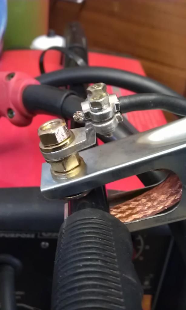
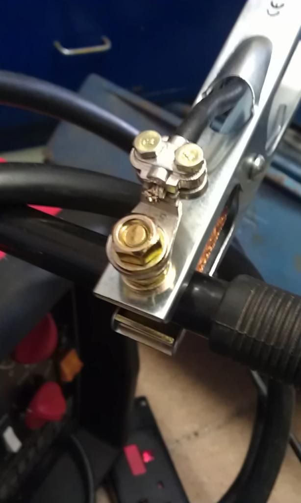
In preparation for my next few sessions I made a few purchases. I bought some new DRONCO Ceramic Flap Discs and a couple of spare Shrouds from Weldequip, I got some new MIG Wire from Machine Mart and bought a new 200 Amp Earth Clamp for my Clarke 160EN. As mentioned previously the supplied one is pretty naff and this one is the Dogs Cahoonas's. I cut off the old one, stripped back the wire and soldered it and then bolted it onto the clamp using a lug that I bought with the Clamp. I got the clamp from Wellington Welding Supplies and it only cost about £4.00.
Here it is (what a beauty!! and it really does help):
First task once in the garage was to make some room around the rear of the Mini, it would have been easier to move the Mini forward but its been chocked up on bricks for storage and seemed to make sense to leave it chocked up as I will be away again?
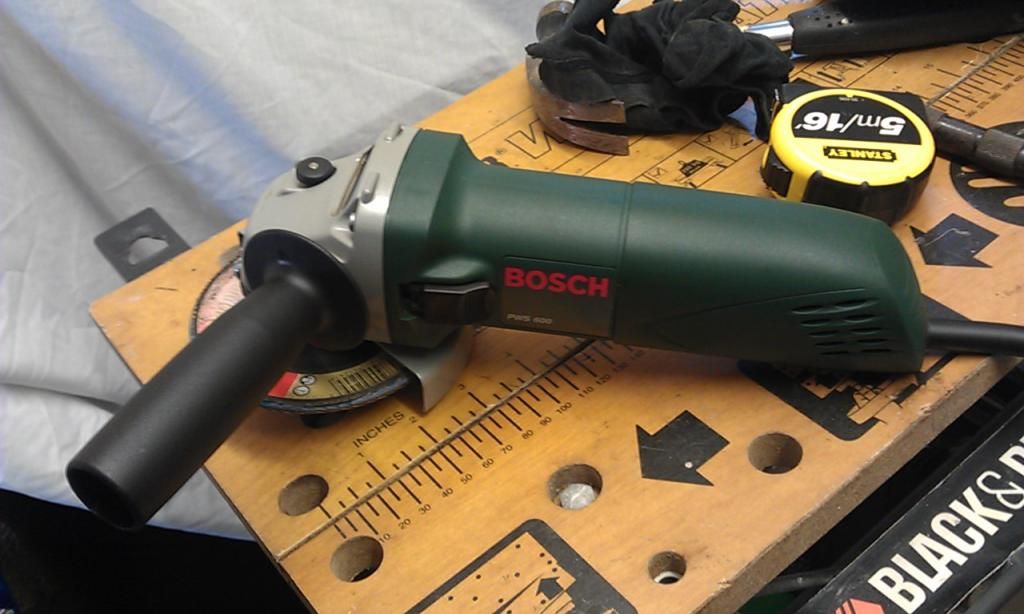
Once the garage was clearer, I set up the workmate, vice, welder and sorted out my tools required for the job, one of which was a recently purchased loverly jubberly brand new Bosh Angle Grinder (my old Grinder finally packed up last trip out).
First of all I bolted the Boot Hinge repair panel in place to mark where it would fit.
I then marked the ends and removed for cutting. Initially I was going to try and leave a little extra overlap of the old panel and attempt to joggle the end of the new panel but due to its shape I decided against this idea instead opting for a Butt Weld.
With the ends marked I cut out the old panel, as I suspected once this was removed the LH and RH light cluster section lost shape instantly (the inner ends spring back towards the front of the Mini. I will now have to be very careful when re-fitting to ensure that the boot still fits.
#13
JonnyAlpha
-
- Members
-
- 2,748 posts
Up Into Fourth
- Location: North Devon
- Local Club: Exmoor Minis
Posted 13 July 2013 - 09:35 PM
04 July 13
Today I started to cut, grind and test fit the Boot Hinge Panel and in doing so it soon became clear that I had to do the Boot Hinge Panel and the Under Rear Light sections simultaneously to ensure all the panels would fit snugly (not an easy task), buying a complete repair panel would have made life a whole lot easier!!!
I ended up spending most of the day preparing the rear end and all of the repair panels for welding, I guess the trick to success is in the preparation ‘prior Planning and Preparation Prevents a P*** Poor Performance (PPPPPPP)’.
To help ensure that the Boot Hinge Repair Panel was in the right place I fitted the Boot to it and when closed was able to use it as a guide.
The Under Rear Light Repair Panels overlap the Boot Hinge Repair Panel so once it was lined up I cut off the overlap on the lip that sits on the boot floor but kept the upright overlap and joggled the edge so that it sat flush behind the Boot Hinge Repair Panel. Doing this meant that it could be Lap Welded rather than Butt Welded which is an easier weld to achieve and will help strengthen the rear end repair.
Welding inside the boot to finish it off will prove a challenge though.
Pic of modified repair panel with home made joggled edge:
Joggle is a bit big (anyone know how to do this better?) Is there a tool? I used a vice, hammer and Brick Bolster.
Once the Boot Hinge Repair Panel was aligned I prepared the RH Under Rear Light Repair Panel it will fit but may need a liberal amount of body filler before painting. There was already a load of filler under the rear RH light but none on the LH side?? I cleaned all of this off before welding.
Once the RH Under Rear Light and Boot Hinge Repair Panel were OK I cleaned off all of the paint on the Rear Light Panels as it did not seem very well primed (Mini Spares Part). I only cleaned of the weld edges of the Boot Hinge Repair Panel, this is a Somerford Mini part and they tend to be primed better. Tools used were a DRONCO Fleece which is excellent for paint removal but I soon remembered it does not work well on edges (BANG) it disintegrated, good job I bought a spare!! I then changed to a Twisted Knot better at getting in tight spaces. I also cleaned up under the rear light and other edges on the remaining mini bodywork and also cleaned up the inside to remove any foreign debris which may affect the weld.
I then marked, centre punched and drilled all of the holes for plug welding the panels to the boot floor. Mig Welding Forum recommends 7.5mm holes for 1mm panels but I only had a 6.5mm drill (what’s 1mm between friends!!), anyway it will butt welded at the edges and I might chuck in a couple of spot welds inside the boot?
Once all the panels were drilled I cleaned up the drill holes with a Ceramic 80 Grit Flap Disc.
All parts were then primed with U-POL Weld Through Primer, this is essential for coating areas between welded panels to prevent rust e.g. where the Boot Hinge Repair Panel overlaps the Boot Floor however I gave everything a thin coat, not required really.
Here's a pic of the Boot Hinge repair panel drilled and primed:
Once the primer was dry I then re-fitted the Boot Hinge Panel to the Boot lined it up and clamped it in place. Getting everything to line up was a knightmare and this is were a full repair panel would have helped £40 v £120 false economy.
Here's some other pics of the work done today:
RH Rear Light Cluster repair panel showing marks for cutting, top line is top of joggled edge of the panel which will sit behind bottom line is the cut line!! The white area to the left is more filler which I removed before welding.
Test fit of the RH Light Cluster and Boot Hinge repair panel:
Now time to weld.
My welder has been out of use for a year, so before I could start I had to prep it (clean it, fit new welding wire (gone rusty), change the tip etc). As mentioned above I also fitted a 200 Amp Earth Clamp purchased from Wellington Welding along with a lug used to hold the wire and bolt to the Earth Clamp.
Here's another pic of it because its sooo good!!
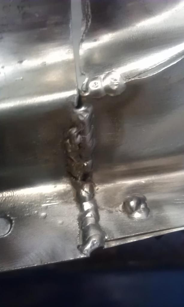
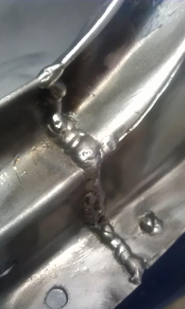
All I managed before wrapping up for the evening were 2 x plug welds – here’s one (The filler at the top is on the bottom of the boot)
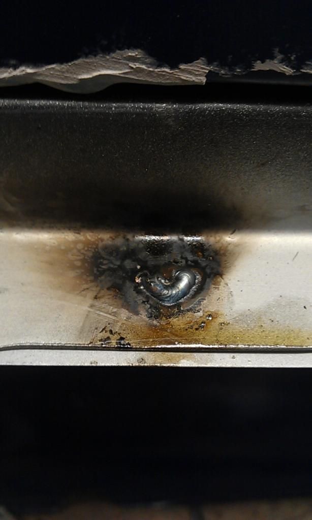
And another:
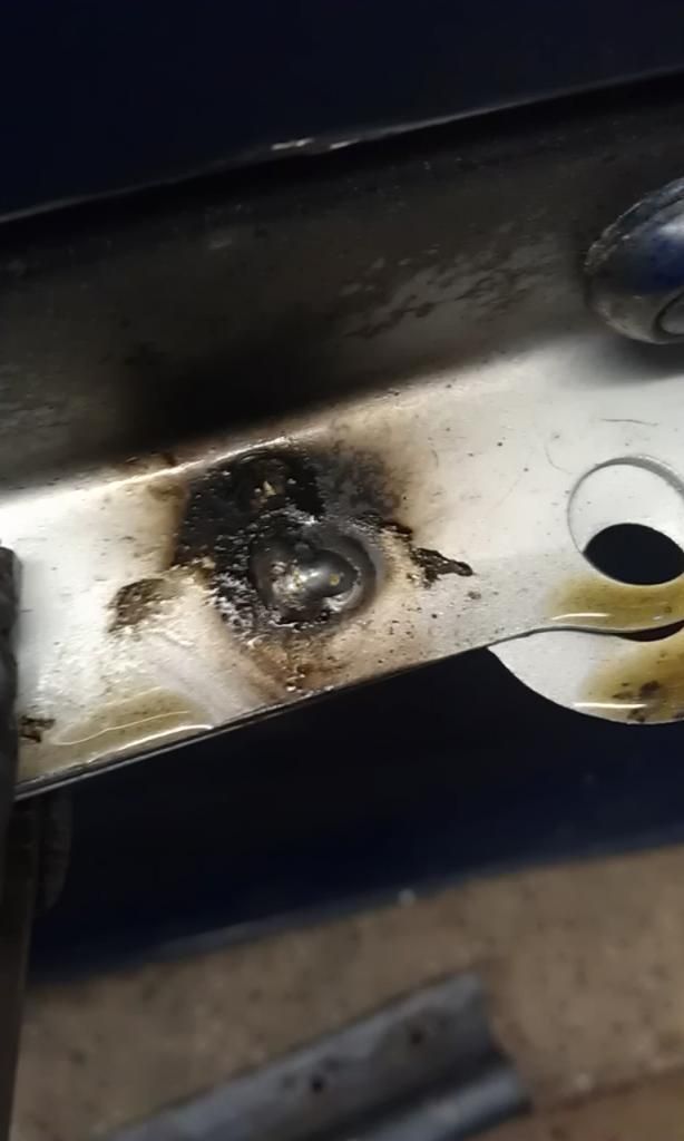
They Look dirty but all the black wiped off, think it was the Anti Spatter paste, (so is the fluid), which I coated the torch in before welding.
And here's a shot showing the penetration:
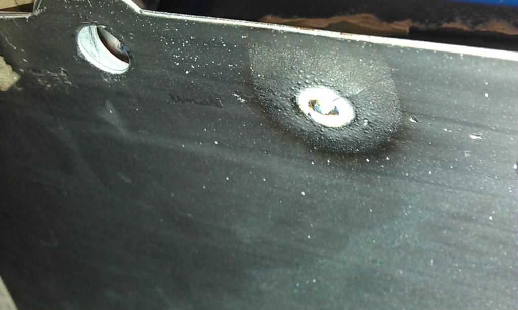
That was it for the evening.
#14
JonnyAlpha
-
- Members
-
- 2,748 posts
Up Into Fourth
- Location: North Devon
- Local Club: Exmoor Minis
Posted 13 July 2013 - 10:02 PM
04 Jul 13
Well a really productive day today as I managed to spend most of the day in the garage.
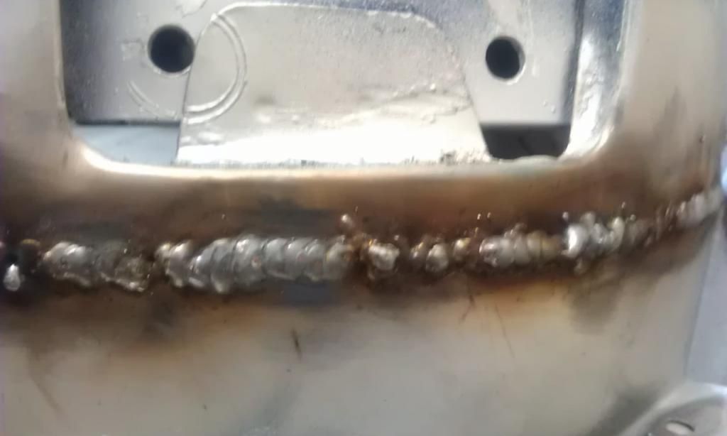
First thing I did was spot weld the left hand end of the boot hinge repair panel to hold it in place then as it was a pretty good fit I butt welded the top lip and curve section.
Next I clamped up the RH Rear Light Cluster Repair Panel and applied 3 x Spot Welds along the section that was the snuggest fit.
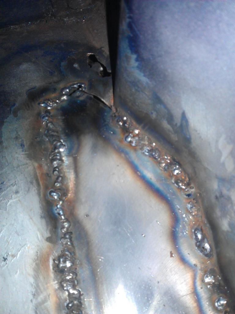
Then I plug welded the LH base of the RH Rear Light Repair Panel and then after a couple of spot welds I butt welded the same panel to the Boot Hinge Panel.
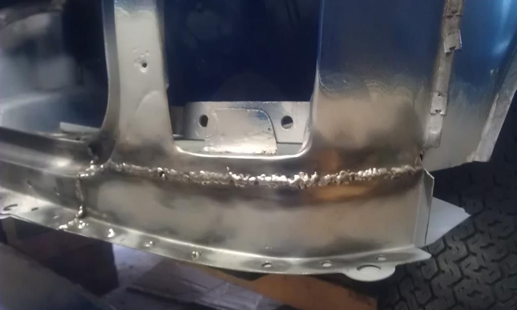
Here's the weld cleaned up, not bad
For the lap welding my Clarke was set to Power Min 2 Wire Speed 7.5 and for the Butt Welding Power was Min 1 Wire Speed 6.
The black residue turned out (I think) to be burnt off Weld Through Primer which I was now getting a lot less because I had removed most of it that I had incorrectly sprayed on visible surfaces (Not required). My welds were a little brown sooty but not half as bad as they had been on previous occasions, this was because I was now getting more confident with the welder and holding the torch at a better angle and closer which was helping the shielding gas to protect the weld. I also found that I had the shielding gas set too low as I had been looking at the wrong part of my Flow Meter, I was reading 10 CHF and not 10 LPM!! These changes showed in the welds as the lap weld on the base and the butt weld were some of the best I had done to date J
I then proceeded to apply a few more spot welds along the Rear Light Cluster Panel join after first applying some panel beating to get a better join, in some case using the base of the wooden hammer handle to apply pressure to hold the panel in place while I welded (not too easy with one pair of hands). All in all it ended up a better fit than I first anticipated.
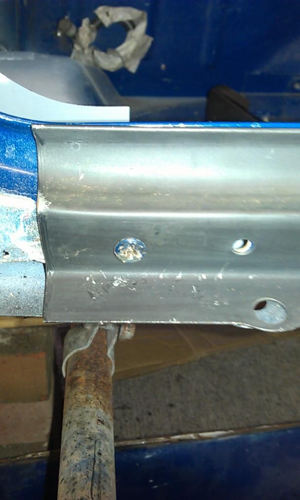
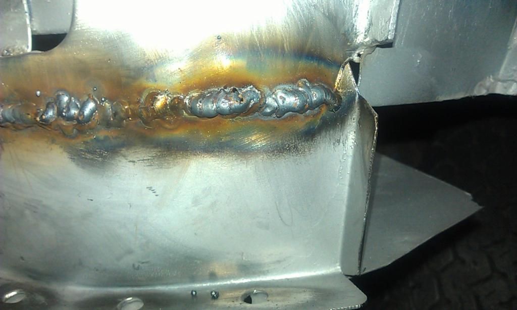
Next I finished off the RH end of the Hinge Repair Panel, I was a pretty bad fit at first but after a tweak with a hammer and a pair of pliers I managed to get it pretty close but still had a pretty large gap in the middle. I spot welded the very top were it joined and then remembered a trick that I had read about on how to fill a large gap in a but weld.
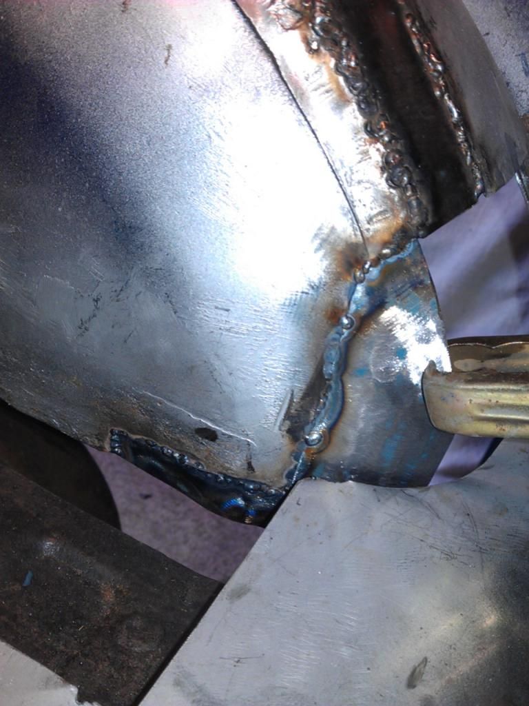
I found a trusty piece of flattened Copper pipe and bent it in shape and clamped it behind the panel. Once in place I proceeded to feed the weld pool bottom to top left to right and managed to successfully fill the gap. The result was (for me) pretty impressive.
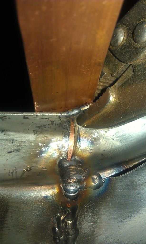
Here's the join:
And here it is cleaned up:
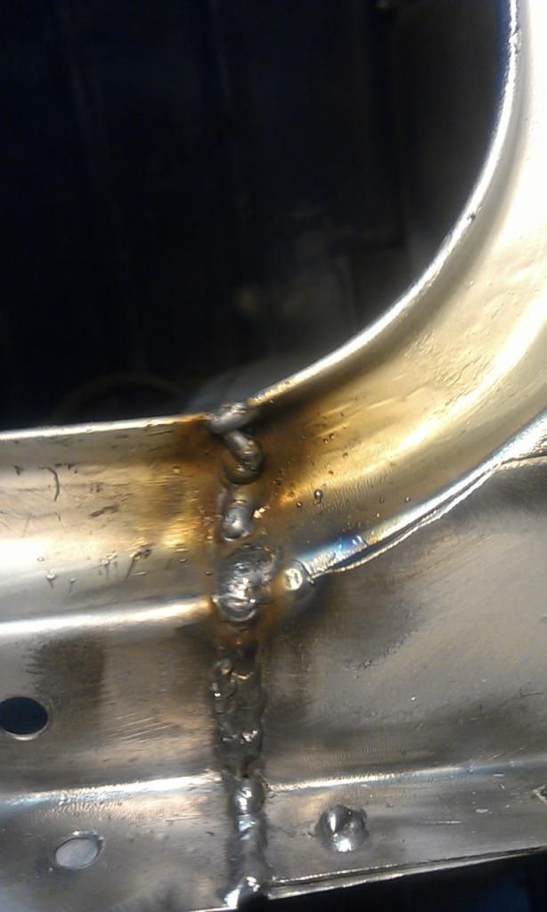
I then finished of seam welding the RH Rear Light Repair Panel but had to play with the settings along the way as my penetration was not as good but that’s because I was seam welding which I guess needed a slightly higher setting. The adjustments showed in the varying quality of the weld. In the end I decided it was partly my technique, I was travelling too fast.
Here is a shot from behind showing the varying penetration whilst playing with the settings:
I finally settled for the settings which are shown further up as they seemed to work best. For the lap welding my Clarke was set to Power Min 2 Wire Speed 7.5 and for the Butt Welding Power was Min 1 Wire Speed 6.
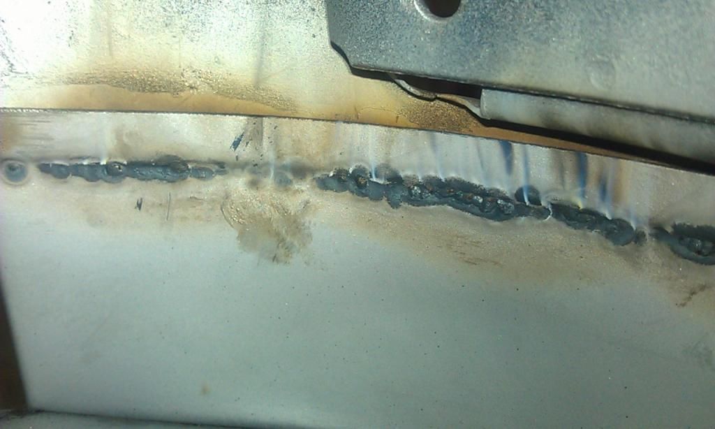
Here it is cleaned up:
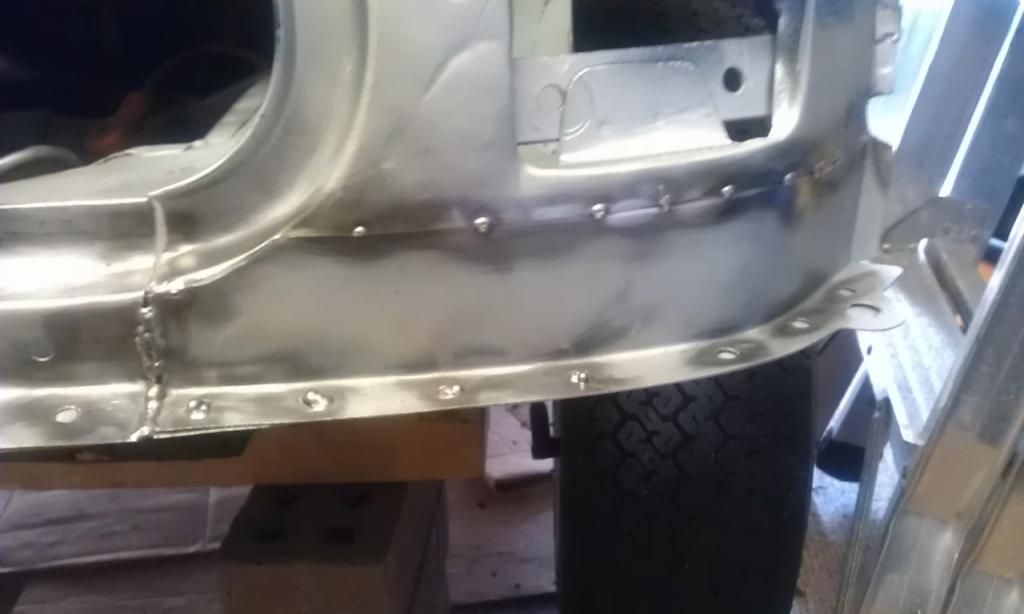
The last job was to finished off all the plug welds on the RH Rear Light Cluster Under Panel and Boot Hinge Panel.
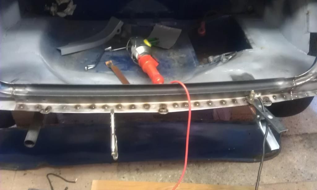
Finally starting to look a whole lot healthier.
Well that was all for this session, next up the LH side.
Edited by JonnyAlpha, 13 July 2013 - 10:04 PM.
#15
JonnyAlpha
-
- Members
-
- 2,748 posts
Up Into Fourth
- Location: North Devon
- Local Club: Exmoor Minis
Posted 21 July 2013 - 04:43 PM
10 Jul 13 - Intermission
After the last bout of welding I came down with a sore throat and runny nose, to be honest I think it was a summer cold however in case it was due to the welding I decided to improve H&S whilst so after some research I found this thread http://www.mig-weldi...ead.php?t=41649
After reading it I ordered a new respirator face mask from Screw Fix (a 3M 4255 Organic Fume and Particulate). Its really comfortable but you must remember to put your glasses on first.
I was previously using this disposable mask http://www.weldequip.com/fume-mask.htm but got my masks mixed up and actually did all the welding with a differnt mask, it was however luckily still rated FFP3.


1 user(s) are reading this topic
0 members, 1 guests, 0 anonymous users


