Jump to content


Photo
- - - - -

Ignition Problem

electrical

Best Answer dklawson , 16 January 2014 - 06:21 PM

If you did not get the light to light with the last ignition module test I described but it worked with points... I agree the electronic module is likely bad.   However, some of the latest (expensive) electronic ignition modules are speed dependent and require that the dizzy shaft is spinning fast for the module to switch.   


Yes, points make a blue spark whey they open if the coil has been charged up.  That is perfectly normal.  Lack of spark or a weak orange spark indicate problems.


EDIT:  Now that you have set the points gap and know that the distributor is working, you will be reinstalling it in the block.  I assume you know that the distributor orientation in the block is not random and that you need to set the static timing to get the engine to fire.  If you are not familiar with static timing, see the thread linked below.  I posted a link in that thread to my PDF article on setting static ignition timing.  The PDF, YouTube, and your service manual will explain the process.


http://www.theminifo...ing-a-camshaft/

Go to the full post


  • Please log in to reply
10 replies to this topic

#1 Oskar

Oskar

    Learner Driver

  • Noobies
  • PipPip
  • 10 posts
  • Location: Southampton

Posted 08 January 2014 - 04:26 PM

Hi there, I'm new to this forum.


I recently bought a 998 1987 City e as my first car project.


The car turned over but didn't start so when I lifted the bonet, I realised that the dizzy was taken apart and was missing the rotor arm and points. I bought the conversion kit for it but what buggs me is that even though the power is comming to the coil, it gives no spark. I thought I was doing something wrong so I connected the coils negative terminal to the old condenser that was in the distributor, coil's positive terminal straight to the battery's positive terminal and I was trying to see if it sparks by putting the coil plug close to the bolt in the engine and no spark was visible. I have also tried the same thing with with no condenser, with the coil connected to the distributor and nothing.


When connecting the positive terminal to the battery, there is power at the negative terminal so the primary winding seems ok. The coil's primary resistance is around 6.5 ohms and the secondary is around 9.3 on the 20k multimeter setting.


Am I doing something wrong, perhaps there is something missing?


#2 dklawson

dklawson

    Moved Into The Garage

  • TMF+ Member
  • PipPipPipPipPipPipPipPipPipPipPip
  • 10,923 posts
  • Name: Doug
  • Location: Durham, NC - USA
  • Local Club: none

Posted 11 January 2014 - 03:04 PM

I do not know your level of experience with points ignition systems so I apologize if anything I say sounds offensive.  It is not meant to.


Points ignition systems do not work by simply making power connections.  Succinctly, current from the ignition switch goes to one side of the coil.  Current flows through the coil to the distributor.  Inside the distributor are the points (a switch) and the condenser.  When the points are closed, current is flowing.  When the points open, current stops flowing.  With the points closed, the flowing current builds up a magnetic field on the low-tension (primary) side of the coil.  When the points open, current flow stops and the coil's magnetic field collapses.  The collapsing magnetic field induces a large, high-voltage spike on the coil's secondary (high-tension) windings and that is what is used to make sparks.  In short, hooking the coil up to the condenser and turning on the ignition will not make sparks.  The condenser's role in this is to both aid in the coil's charge/discharge and to reduce the arc across the points.  The condenser is not used when electronic ignitions are fitted.


You said you bought a conversion kit for the car.  I assume you mean electronic ignition.  What did you buy and how is it presently wired?


The low-tension resistance you measured (6.5 Ohms) is too high. Please repeat your measurement with NO WIRES on the coil low-tension terminals.  The presence of wires on the coil can affect the readings.  Also, check your meter.  Make your resistance measurement on the coil and write the value down.  Now connect the meter's probes together and wait for the reading to stabilize.  Any non-zero resistance shown when holding the probes together is the resistance of the meter's probes and that must be subtracted from the coil measurement you made.


If the link below works (it sometimes doesn't) it is a direct download link to a PDF on points ignition systems.  Even with the electronic ignition conversion fitted you may find it helpful when trying to understand how the ignition is supposed to work.  The fundamentals are the same but with electronic ignitions, you have an electronic switching module that replaces the points and condenser.

https://sites.google...redirects=0&d=1


#3 GreenMini17

GreenMini17

    Formally known as Chris-G

  • Members
  • PipPipPipPipPip
  • 424 posts
  • Location: South

Posted 11 January 2014 - 03:07 PM

Do you have 12-13volts at the battery? I.e do you have a good battery?

#4 Oskar

Oskar

    Learner Driver

  • Noobies
  • PipPip
  • 10 posts
  • Location: Southampton

Posted 11 January 2014 - 07:38 PM

Firstly, I'm not in anyway offended, I have little knowledge when it comes to electrics, hence why I'm here asking for support.

Secondly, thank you very much for the effort explaining what I could'nt find on google.

That clears it out a lot. Correct me if I'm wrong but in easier terms it seems like the coil builds up the magnetic field by the negative terminal being grounded and when the ground connection "vanishes", the condenser makes the coil discharge through the high tension winding and hence the spark?

Yes, the conversion is the electronic ignition from powerspark. The way it is supposed to be wired is red cable to coils positive terminal, black to negative and power from the switch also to the coil's positive terminal. My worry is that due to previous coil connections (one comming from the alternator), as the ignition module is polarity sensitive, I could've fried the ignition module. Is there any chance of bench checking it? All the tests I have done before were out of the car. When the dizzy with the electronic module was in the car, it created no spark from the beginning, it may be because it was fried at the very beginning due to the dodgy connection.

Tge battery in the car turns the engine over but the voltage is just about 12 volts when unplugged.

#5 dklawson

dklawson

    Moved Into The Garage

  • TMF+ Member
  • PipPipPipPipPipPipPipPipPipPipPip
  • 10,923 posts
  • Name: Doug
  • Location: Durham, NC - USA
  • Local Club: none

Posted 12 January 2014 - 02:30 AM

You have a good understanding of what is going on with the coil.


You can test the module.  There are several thing you can do.  


Start by confirming that you have 12V to the module.  Turn the ignition on and use your meter to measure the voltage between coil(+) and ground.  You should see battery voltage.  If you don't, there is a supply problem to sort out.


If you have 12V on coil(+), test the module by itself.  Disconnect the module's black wire from coil(-) and connect a test light bulb between coil (+) and the module's black wire.  The light will take the place of the coil.  Turn the engine over on the starter.  The light should flash on and off.  If it does, the module is working.  If it doesn't, the module is not working.


#6 Oskar

Oskar

    Learner Driver

  • Noobies
  • PipPip
  • 10 posts
  • Location: Southampton

Posted 13 January 2014 - 08:51 PM

I have done so with the distributor out from the car just now. I connected the red module wire to the positive terminal on the battery, and I've put the tester light between the module's black wire and the battery's negative terminal. When turning the distributor shaft by hand, the tester did not light at all. It seems like the module has been damaged at the very beginning, well my bad and my 30 quid pretty much thrown in the waste bin however, man learns on his mistakes. I bought a set of two standard points with condensers, a dizzy cap and a rotor arm for just under a tenner on the weekend, I know buying parts without being sure the current ones are not working is not a wise idea however the price was pretty good for the set and I was almost certain the module was not working as everything indicated it. I'll have the parts within the next two days, I will sort the engine out using the points and then once I will be sure all the connections are the way they should be, I will order another module and fit it in and keep the points as spares.


I heard there is supposed to be an air gap somewhere, either between the points or the point arm and the dizzy shaft, is that right? And if so do you have any clue what the gap should be?


In terms of the coil's resistency on the primary winding, once checked again, it shows 4.4 ohms so after taking away around .9 ohm of the probes' resistency, it leaves me with 3.5 ohms, I suppose its a little bit better than before.


#7 dklawson

dklawson

    Moved Into The Garage

  • TMF+ Member
  • PipPipPipPipPipPipPipPipPipPipPip
  • 10,923 posts
  • Name: Doug
  • Location: Durham, NC - USA
  • Local Club: none

Posted 14 January 2014 - 12:53 AM

I have done so with the distributor out from the car just now. I connected the red module wire to the positive terminal on the battery, and I've put the tester light between the module's black wire and the battery's negative terminal. When turning the distributor shaft by hand, the tester did not light at all. .


Not quite.  The connections you made are not correct.  Remember that the electronic ignition module is basically a switch.  It provides a path to earth for current flowing through the ignition coil and the black wire IS a path to earth.  When you connected your test lamp to battery negative and to the  black wire... that was like connecting both sides of the test lamp to negative so your test did not indicate if the module is good or bad.


Since the dizzy is out of the car, repeat your test as follows.

Connect the red wire to battery (+)

Connect the dizzy body to battery (-)  {***See my comment below}

Connect your test lamp between the black wire AND battery (+). 

Spin the dizzy shaft by hand while watching the test lamp.  If the module is working the lamp should turn on and off.


*** The electronic ignition module needs power and an earth connection AND it must provide a path to earth for the load (the coil or your test light).  The mounting foot of the module IS its earth connection.  Therefore, when testing the module out of the car, you MUST provide an earth connection to the distributor body for the electronic module to work.  


I heard there is supposed to be an air gap somewhere, either between the points or the point arm and the dizzy shaft, is that right? And if so do you have any clue what the gap should be?

 
I assume you are referring to the points gap.  I cannot stress enough that you need to read through a service manual to get the correct value and to see the steps involved.  However, I will provide an overview here.  
 
You mount the points on the breaker plate and tighten the screws a bit, but not fully.  You rotate the dizzy shaft until the plastic block on the moving arm of the points is resting on the TOP of one of the 4-lobes on the dizzy shaft.  While in that position you use a screwdriver on the base of the points (there should be notches and tabs) to pry the points apart until you have a gap of about 0.016 inches.  You do not set this by eye, you use feeler gauges.  The gap is "right" when there is just a slight bit of drag on the feeler gauge as you pull it out of the points gap.  Then you tighten the mounting screws a bit more AND go back and check the gap again.  You will likely have to do this several times as the points gap typically changes as you tighten the mounting screws.  When the dizzy is in the engine block you can use one screwdriver to hold the points in place while you tighten the mounting screws.  I strongly encourage you to read a service manual and search YouTube for videos on the process.  It is best learned by watching someone do this, or preferably "hands on" with guidance, not just watching.
 

In terms of the coil's resistency on the primary winding, once checked again, it shows 4.4 ohms so after taking away around .9 ohm of the probes' resistency, it leaves me with 3.5 ohms, I suppose its a little bit better than before.


The resistance value often quoted for standard coils is 3 Ohms but that is nominal.  Your 3.5 Ohm reading is perfectly fine.  The value you listed in your first post was very high.


#8 Oskar

Oskar

    Learner Driver

  • Noobies
  • PipPip
  • 10 posts
  • Location: Southampton

Posted 16 January 2014 - 04:39 PM

Ok, after connecting the module the way you told me, the test light didn't light at all, looks like my predictions were right.

As to fitting in the point breaker, I managed to fit it in although I had to find out what 0.016" was in metric system as I only had metric feeler gagues, its about .4 of a milimeter, it looks right as I found specs which say that the gap should be somewhere between .35 and .4 on metric gagues.


I have the spark now which I am really happy about :) One question though, the points when they are breaking create a tiny blue spark, I'm not sure if that is supposed to be happening, have you got any advice on that? May that be that the gap is too small or too big?


#9 dklawson

dklawson

    Moved Into The Garage

  • TMF+ Member
  • PipPipPipPipPipPipPipPipPipPipPip
  • 10,923 posts
  • Name: Doug
  • Location: Durham, NC - USA
  • Local Club: none

Posted 16 January 2014 - 06:21 PM   Best Answer

If you did not get the light to light with the last ignition module test I described but it worked with points... I agree the electronic module is likely bad.   However, some of the latest (expensive) electronic ignition modules are speed dependent and require that the dizzy shaft is spinning fast for the module to switch.   


Yes, points make a blue spark whey they open if the coil has been charged up.  That is perfectly normal.  Lack of spark or a weak orange spark indicate problems.


EDIT:  Now that you have set the points gap and know that the distributor is working, you will be reinstalling it in the block.  I assume you know that the distributor orientation in the block is not random and that you need to set the static timing to get the engine to fire.  If you are not familiar with static timing, see the thread linked below.  I posted a link in that thread to my PDF article on setting static ignition timing.  The PDF, YouTube, and your service manual will explain the process.


http://www.theminifo...ing-a-camshaft/


Edited by dklawson, 16 January 2014 - 06:26 PM.


#10 Oskar

Oskar

    Learner Driver

  • Noobies
  • PipPip
  • 10 posts
  • Location: Southampton

Posted 17 January 2014 - 03:29 PM

The car seems to be willing to come back to life.


I have set the static timing, to 8 degrees BTDC, I connected the coil to the wire coming from the alternator which seems to be giving power non stop, I poured 5l or petrol, sprayed some engine start stuff into the carb and of it went! - for 2 seconds :(


The battery is flat, I'm waiting for my friend who will jump start me as my jump starter didn't come back from my family member who I've lent it to.


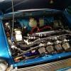
The good news is that it fired up, and it seems like it will run when I will have some assistance as the previous owners disconnected the choke cable. The bad news is that some hoses coming in/out from the carb are absolutely rubbish and need replacing asap. Another thing is that I can't really identify all the hoses coming into the carb apart from the vacuum hose that will go to the dizzy and the fuel hose coming from the air filter. Maybe my friend will have some other ideas.


One question, what is the metal pipe that runs from below the engine, through the front, behind the grill, above wheel arches and enters the carb into one of the two intakes? The second intake is the fuels hose coming from the filter.


EDIT.


I took a closer look at that hose, it looks like a carb overfill hose, I was wondering why it went from the carb, all the way down underneath the engine, now it makes perfect sense. We also jump started the car, stuck the choke on, put some engine start spray and this time it started up nicely, it did of course have a delayed throttle response and died a couple of times but otherwise it runs smoothly with no rattling or anything. My friend's brother is coming over to his for the weekend and he said he will look at the wires etc. so that I won't have to disconnect the coil to stop the engine. We will also set proper timing for it, see if the carb needs cleaning and all the other bits and bobs that will need sorting.


I guess this thread now deserves to be marked as SOLVED as the engine is running and I see no other brick walls ahead of me so far.


I owe dklawson a massive create of finest beer for his detailed information and time he spent solving my issue. I guess I will be seeing you a lot more often now that the project only begins :)


Thanks again and I will be 'seeing' you around :)


Edited by Oskar, 17 January 2014 - 11:32 PM.


#11 dklawson

dklawson

    Moved Into The Garage

  • TMF+ Member
  • PipPipPipPipPipPipPipPipPipPipPip
  • 10,923 posts
  • Name: Doug
  • Location: Durham, NC - USA
  • Local Club: none

Posted 18 January 2014 - 02:20 AM

You are more than welcome and I am really happy for you that you have gotten the engine going !  Keep in mind that with any restoration there will be setbacks and problems.  Hang in there and stick to it.  Do a little each day and you will get there!


Also tagged with one or more of these keywords: electrical

1 user(s) are reading this topic

0 members, 1 guests, 0 anonymous users