Jump to content


Photo
- - - - -

Ignition Coil Wires


Best Answer dklawson , 08 August 2014 - 05:23 PM

OK, in the picture above, you do indeed show that the distributor has points.  Follow the wire leaving the distributor and connect it to coil (-) regardless of where it is connected now.


The white/yellow and white/pink wires go on coil (+).  If you have a white/black wire (and if the white/black wire is not connected to the one leaving the distributor...) leave the white/black wire disconnected and taped off for now.  It may be for a tachometer if fitted.


You asked how to know the firing order.  Go back to page 1 of this thread and the link I posted for the FAQ article.  It shows the cylinder order and the FACTORY orientation of the plug wires around the cap.  You need to confirm if this is still correct for your car.  How?  Download and read my PDF on static timing (link below).  To be accurate there is more to static timing than pointing the rotor in the general direction of a certain lug on the distributor cap. 


Don't assume the distributor drive gear in the block is in the correct orientation to go by the factory positions for the plug wires on the cap.  Read my PDF. The later section of the document will explain how to find and confirm piston #1 is near TDC on its FIRING stroke and how to position the spark plug wires based on what you find.   (Page 5, Firing Order).


So... look at the picture in the FAQ link. 

Read the PDF on static timing.

Find the static timing location around 5 to 8 BTDC for #1 on its firing stroke.

Pay attention to the section discussing placing plug wires around the dizzy cap.  (PDF Page 5, Firing Order).

Place the plug wires in the necessary locations on the cap (based on your findings... not what the factory pictures show)

Set the static timing.

Test for spark at a spark plug by removing a plug, resting it on the cylinder head, and turning the engine over on the starter.


www.sites.google.com/site/purlawson/home/files/StaticTiming%5B1%5D.pdf

Go to the full post


  • Please log in to reply
40 replies to this topic

#16 BronkoMini

BronkoMini

    One Carb Or Two?

  • Members
  • PipPipPipPipPipPipPip
  • 1,484 posts
  • Location: Wiltshire
  • Local Club: Mini Fixers

Posted 08 August 2014 - 04:42 PM

Agreed.

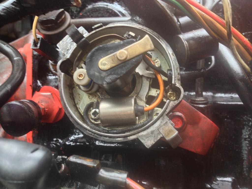
If two wires are coming out of the distributor, that's for an electronic ignition.  If in doubt, post pictures of the distributor with the cap removed.


The white/pink and white/yellow wires are used with ballast ignition systems.  If you do still have points in the distributor, the low-tension wiring you describe above is correct.  IF inside the distributor you have an aftermarket electronic ignition, there are issues to sort out.


When you put the distributor from the old engine in the new one did you do anything to set the timing?  This is important as it may affect both the spark plug wire order AND whether or not the engine will start and run.

Im just up loading some pictures now.

I followed the Haynes manual on how to set static timing, by seeing when no 1 piston hit tdc on the compression stroke and turned the distributer in line with the rotor arm with no 1 lead, but I did this starting at the left of the engine, which is no 4 you say?


#17 Badboytunes

Badboytunes

    Camshaft & Stage Two Head

  • Members
  • PipPipPipPipPipPipPipPip
  • 1,615 posts
  • Location: Northampton
  • Local Club: MINIS Unleashed

Posted 08 August 2014 - 04:57 PM

No1 cyl is by the radiator.


#18 BronkoMini

BronkoMini

    One Carb Or Two?

  • Members
  • PipPipPipPipPipPipPip
  • 1,484 posts
  • Location: Wiltshire
  • Local Club: Mini Fixers

Posted 08 August 2014 - 05:01 PM

No1 cyl is by the radiator.

Do you know the firing order? thanks


#19 BronkoMini

BronkoMini

    One Carb Or Two?

  • Members
  • PipPipPipPipPipPipPip
  • 1,484 posts
  • Location: Wiltshire
  • Local Club: Mini Fixers

Posted 08 August 2014 - 05:03 PM

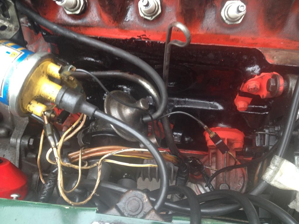
You can see the two black wires, one going to the coil and the other attaching to the other white wire.

F95F62D9-0D09-4E74-AEE7-4042E3F76857_zps

The dizzy

05995E56-11D8-4BF8-B013-6105CCF28D42_zps


#20 dklawson

dklawson

    Moved Into The Garage

  • TMF+ Member
  • PipPipPipPipPipPipPipPipPipPipPip
  • 10,923 posts
  • Name: Doug
  • Location: Durham, NC - USA
  • Local Club: none

Posted 08 August 2014 - 05:23 PM   Best Answer

OK, in the picture above, you do indeed show that the distributor has points.  Follow the wire leaving the distributor and connect it to coil (-) regardless of where it is connected now.


The white/yellow and white/pink wires go on coil (+).  If you have a white/black wire (and if the white/black wire is not connected to the one leaving the distributor...) leave the white/black wire disconnected and taped off for now.  It may be for a tachometer if fitted.


You asked how to know the firing order.  Go back to page 1 of this thread and the link I posted for the FAQ article.  It shows the cylinder order and the FACTORY orientation of the plug wires around the cap.  You need to confirm if this is still correct for your car.  How?  Download and read my PDF on static timing (link below).  To be accurate there is more to static timing than pointing the rotor in the general direction of a certain lug on the distributor cap. 


Don't assume the distributor drive gear in the block is in the correct orientation to go by the factory positions for the plug wires on the cap.  Read my PDF. The later section of the document will explain how to find and confirm piston #1 is near TDC on its FIRING stroke and how to position the spark plug wires based on what you find.   (Page 5, Firing Order).


So... look at the picture in the FAQ link. 

Read the PDF on static timing.

Find the static timing location around 5 to 8 BTDC for #1 on its firing stroke.

Pay attention to the section discussing placing plug wires around the dizzy cap.  (PDF Page 5, Firing Order).

Place the plug wires in the necessary locations on the cap (based on your findings... not what the factory pictures show)

Set the static timing.

Test for spark at a spark plug by removing a plug, resting it on the cylinder head, and turning the engine over on the starter.


www.sites.google.com/site/purlawson/home/files/StaticTiming%5B1%5D.pdf


#21 GraemeC

GraemeC

    Crazy About Mini's

  • TMF+ Member
  • PipPipPipPipPipPipPipPipPipPip
  • 7,318 posts
  • Location: Carnforth

Posted 08 August 2014 - 05:50 PM

One of the wires from the dizzy is actually from a suppressor fastened to the side of the dizzy.

If the wire coming from within the distributor cap is the one you previously had connected directly to the coil then you need to put as new spade on it - the crimp is in a bad way and could fail easily and leave you stranded (once you get going :D  )


Edited by GraemeC, 08 August 2014 - 05:50 PM.


#22 BronkoMini

BronkoMini

    One Carb Or Two?

  • Members
  • PipPipPipPipPipPipPip
  • 1,484 posts
  • Location: Wiltshire
  • Local Club: Mini Fixers

Posted 08 August 2014 - 07:51 PM

Thanks I shall try that tomorrow

#23 egoist

egoist

    On The Road

  • Noobies
  • PipPip
  • 43 posts
  • Location: Norwich

Posted 08 August 2014 - 08:17 PM

Maybe someone can tell me why Pink with White coil wire getting hot when ignition is on?


#24 Dan

Dan

    On Sabbatical

  • TMF+ Member
  • PipPipPipPipPipPipPipPipPipPipPip
  • 21,354 posts

Posted 08 August 2014 - 08:25 PM

The little can with the wire coming out of it that is screwed to the dizzy shouldn't be there, unscrew it and disconnect it. If anything it should be connected to the coil bracket as an ignition interference suppressor but for the purposes of getting the thing running you don't need it. It's not part of the dizzy. The wire you need to connect to the white cable is the one actually emerging from the dizzy itself.

As above cylinder 1 is at the radiator end. The front of nearly all engines is considered to be the end where the timing gears are. The cylinders are 1,2,3,4 right to left across the block. The order is 1,3,4,2 around the dizzy anti-clockwise from where the rotor is pointing when cylinder 1 is firing, usually at roughly the 1 o'clock position in a Mini.

#25 Dan

Dan

    On Sabbatical

  • TMF+ Member
  • PipPipPipPipPipPipPipPipPipPipPip
  • 21,354 posts

Posted 08 August 2014 - 08:26 PM

Maybe someone can tell me why Pink with White coil wire getting hot when ignition is on?


Because there is power running through it. The pink/white wire is a resistor.

#26 egoist

egoist

    On The Road

  • Noobies
  • PipPip
  • 43 posts
  • Location: Norwich

Posted 08 August 2014 - 08:29 PM


Maybe someone can tell me why Pink with White coil wire getting hot when ignition is on?


Because there is power running through it. The pink/white wire is a resistor.


So that's normally?


#27 Dan

Dan

    On Sabbatical

  • TMF+ Member
  • PipPipPipPipPipPipPipPipPipPipPip
  • 21,354 posts

Posted 08 August 2014 - 08:48 PM

It should be quite warm but not stupidly hot, be careful because they have been known to start fires. Is it hot if the engine is running or just when it's sat with the ignition switched on but the engine off?

#28 egoist

egoist

    On The Road

  • Noobies
  • PipPip
  • 43 posts
  • Location: Norwich

Posted 08 August 2014 - 08:57 PM

It should be quite warm but not stupidly hot, be careful because they have been known to start fires. Is it hot if the engine is running or just when it's sat with the ignition switched on but the engine off?

Didn't check with engine running, was checking the wires with tester when ignition is on.


#29 BronkoMini

BronkoMini

    One Carb Or Two?

  • Members
  • PipPipPipPipPipPipPip
  • 1,484 posts
  • Location: Wiltshire
  • Local Club: Mini Fixers

Posted 08 August 2014 - 09:18 PM

The little can with the wire coming out of it that is screwed to the dizzy shouldn't be there, unscrew it and disconnect it. If anything it should be connected to the coil bracket as an ignition interference suppressor but for the purposes of getting the thing running you don't need it. It's not part of the dizzy. The wire you need to connect to the white cable is the one actually emerging from the dizzy itself.
As above cylinder 1 is at the radiator end. The front of nearly all engines is considered to be the end where the timing gears are. The cylinders are 1,2,3,4 right to left across the block. The order is 1,3,4,2 around the dizzy anti-clockwise from where the rotor is pointing when cylinder 1 is firing, usually at roughly the 1 o'clock position in a Mini.

Thanks

#30 KernowCooper

KernowCooper

    Sparkie

  • Mini Docs
  • PipPipPipPipPipPipPipPipPipPip
  • 7,847 posts
  • Name: Dave
  • Location: The South West
  • Local Club: Kernow Mini Club

Posted 09 August 2014 - 08:52 AM

The White/pink is the resister wire dropping the voltage to a ballast coil to 9v, like Dan has pointed out it should not be hot enough that you can't hold it in your hand, if it is that hot the resister in the wire is running hot and can burn the loom through. This wont happen though to start the car with your issue but something you need to keep a eye on once you have resolved your starting problem and then do the 12v new coil and feed conversion.


0 user(s) are reading this topic

0 members, 0 guests, 0 anonymous users