


Looks like the coil is for ballasted, so you'll need a ballasted supply (pink/white) to avoid melting.
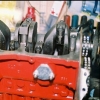
The other pictures are of a solenoid for an inertia starter motor. The terminal with the nut on the left it attached to the battery cable, so is permanently live. It has a collection of brown wires attached. A couple collect charge from the alternator and the others supply it to the rest of loom. The pink/white is only supplied when the ignition is on so it shouldn't be anywhere near there. The other terminal with a nut supplies the starter motor, but only when it's actuated. The red/white wire on its own terminal in piccy one does that when you turn they key all the way. There should be a similar terminal on the opposite side of the solenoid, that's where the yellow/white should attach. However, they do make solenoids without it for unballasted cars.
That looks like the yellow wire, on the left of the 2nd piccy, where does it go?
Hi Ethel. I attach 2 photos and although hard to be 100% sure without taking that air inlet out (how the heck does that come out....will figure it out if necessary), 95% sure it must go into that central connection. This is one connection I haven't been able to clean up and looks like it would benefit from it. Could it be as simple as that? Although, all trouble happened with the jumpstarting.
This them, assuming there is only one yellow/white wire in the set up, goes to the coil as per photo A. Does this help? Please let me know what other photos might help, or what I could try next. Thanks a lot!. A.JPG 32.76K
2 downloads
B.JPG 28.94K
2 downloads
A.JPG 32.76K
2 downloads
B.JPG 28.94K
2 downloads


 . It has its own spade terminal, like the red/white on the other side. That's because it needs to be isolated, so it doesn't mess with the coil when it's not active. It could do that in 2 ways: either by supplying a "full fat" 12v to the ballast coil that would cause overheating, or by earthing & acting as a voltage divider so even less voltage is across the coil than it should get via the ballast wire.


