Would it be possible for you to post anymore pictures of the throttle pedal setup please?

73 fast road mini
Started by
Chris C
, Aug 09 2007 06:03 PM
305 replies to this topic
#91

Jobu
-

- Members
-

- 508 posts
Super Mini Mad
- Local Club: 16vminiclub
Posted 15 November 2008 - 01:10 PM
#92
BigRed8
-
- Noobies
-
- 28 posts
Passed Test
- Local Club: N/A
Posted 15 November 2008 - 01:11 PM
Modification and installation of Honda shift linkage and shift lever.
Like most things on this project, shortening the shift rod and extension rod and then mounting the shifter assembly underneath the floor turned out to be much more complex than expected. This particular Mini’s original transmission was an automatic so I’m sure there are differences from manual gearbox models with respect to the cover plate and maybe in other areas also.
In order to make the Honda Civic extension and shifter rods fit the Mini they both need to both shortened about 12” and bent to run up the tunnel and then make a sharp right/left S turn to line up with their mounting points on the transmission. Because of the complex reshaping of the rods required I found it very difficult to simply measure, cut out a section of the rods, and weld the remaining halves together. What I did instead was:
1) Obtain some steel rod with an outside diameter that is a close fit to the inside diameter of the Honda shifter and extension rods. It turns out that a 20mm OD rod fits perfectly.
2) Cut the rods on both sides of the section that would need to be bent into the S shape and then cut out about 11 inches out of the remaining straight sections of the rods.
3) Bend the S shaped curve sections using a hydraulic pipe bender. This was not easy as the rods had to be “unbent” from the Honda shape and then re-bent into the required Mini shape. I did put a few dents and extra kinks in the tubing. If I were to do it again I’d probably use some new straight tubing and find a better tube bender than the one I have!
4) Cut four 4” sections of the 20mm rod to slip fit the three sections of each rod together.
5) Mounted the rods into the car and adjusted the slip fit joints to get the right length and fit.
6) After several iterations of shortening the Honda rods or in one case adding back additional rod length I got the rods to fit correctly. I then wrapped electrical tape a couple of times around each joint to hold it’s position.
7) After removing the rods I then drilled and tapped holes through the outside Honda rods and the 20mm inside rods on each side of each join to fix the rods in position using M4 bolts. I did this so that I could have the rods ridgid enough to shift gears and make sure I had clearance for the full range of movement required.
8) I installed the "bolted together" rods shifted through the gears. Sure enough there were a few more adjustments eeded so AI re-drilling and taped a couple of the holes and tested it out again. Only then did I weldthe circumference of the tubes together at each of the joints, ground down the welds and painted the rods with primer.
9) The end result is not particularly pretty but it is strong and it fits.
 Shift_rod_1w.jpg 21.03K
43 downloads
Shift_rod_1w.jpg 21.03K
43 downloads
Shift_rod_2w.jpg 15.1K
28 downloads
Mounting the shifter and positioning the rods:
Using a hole saw I cut a 2 1/4” hole in the top of the floor panel cover and ran some rubber edge trim around the interior of the cut out.
Shifter_1008.jpg 453.78K
45 downloads
To mount the shifter mechanism under the panel in the tunnel I tried just mounting a small plate and the rubber piece that holds the “tail” of the extension rod assembly at the back edge of the floor opening. Because there is only about ¾” between the back of the floor opening and the front of the box section cross brace that runs the width of the floor, I could not make the mount stable enough without drilling additional mounting holes up through the box section which I wanted to avoid.
So I went the other direction and created a plate that extends forward past the front edge of the floor opening. It was made entirely out of local hardware store aluminum bar stock and 1/4” aluminum plate. I then cut a 3” hole in that plate and bent the “legs” of the bracket to fit the curved underside of the tunnel. I now had a solid platform to mount the shift bar. This bracket also allowed me to adjust the height of the extension rod and shift rod to allow a straighter path for the rods extending to the transmission. It is easier to show in pictures than to describe.
shifter_1614.jpg 430.83K
21 downloads
shifter_519.jpg 587.1K
19 downloads
This is the underside of the bracket with the mounting bolts and spacer plate for the extension rod “tail” holding rubber piece.. As with the cover plate I also put some rubber trim around the inside of the hole .
shifter_18w.jpg 17.15K
27 downloads
I also had a 50mm ID aluminum kart axle collar lying around the garage that fit around the extension rod “neck” perfectly leaving about 3/8” between the outside of the collar and inside of the hole in the bracket. This should allow adequate movement of the shifter assembly (which is hard mounted to the transmission case via the extension rod) relative to the chassis mounted bracket. It collar doesn’t actually do much except fill in the empty space around the neck but it fit perfectly and looks like it was made to be there. I’ve long since sold the kart so the collar is now part of the Mini!
Shifter_6w.jpg 17.32K
36 downloads
Here is the bracket from the side with the shift lever and extension rod assembly installed.
shifter_8w.jpg 16.45K
20 downloads
A view from the top
shifter_14w.jpg 19.43K
52 downloads
View of the bracket mounted in the tunnel looking forward. In the center is the back end of the extension rod “tail” that rubber mounts to the chassis in the original Honda. It’s going to be a tight fit when it comes time to route the exhaust pipe down the tunnel but I’ll cross that bridge when I come to it.
shifter_13w.jpg 25.6K
36 downloads
The shift rod (on left) and extension rod extending forward from the bracket to their transmission mounting points.
Shifter_12w.jpg 21.95K
30 downloads
A top view of the floor panel with the bracket and shifter in place underneath. When I find a suitable shift lever boot I’ll install it over the opening.
The end result of all this is probably way overkill but it works and has a solid feel to the shift lever movement.
Like most things on this project, shortening the shift rod and extension rod and then mounting the shifter assembly underneath the floor turned out to be much more complex than expected. This particular Mini’s original transmission was an automatic so I’m sure there are differences from manual gearbox models with respect to the cover plate and maybe in other areas also.
In order to make the Honda Civic extension and shifter rods fit the Mini they both need to both shortened about 12” and bent to run up the tunnel and then make a sharp right/left S turn to line up with their mounting points on the transmission. Because of the complex reshaping of the rods required I found it very difficult to simply measure, cut out a section of the rods, and weld the remaining halves together. What I did instead was:
1) Obtain some steel rod with an outside diameter that is a close fit to the inside diameter of the Honda shifter and extension rods. It turns out that a 20mm OD rod fits perfectly.
2) Cut the rods on both sides of the section that would need to be bent into the S shape and then cut out about 11 inches out of the remaining straight sections of the rods.
3) Bend the S shaped curve sections using a hydraulic pipe bender. This was not easy as the rods had to be “unbent” from the Honda shape and then re-bent into the required Mini shape. I did put a few dents and extra kinks in the tubing. If I were to do it again I’d probably use some new straight tubing and find a better tube bender than the one I have!
4) Cut four 4” sections of the 20mm rod to slip fit the three sections of each rod together.
5) Mounted the rods into the car and adjusted the slip fit joints to get the right length and fit.
6) After several iterations of shortening the Honda rods or in one case adding back additional rod length I got the rods to fit correctly. I then wrapped electrical tape a couple of times around each joint to hold it’s position.
7) After removing the rods I then drilled and tapped holes through the outside Honda rods and the 20mm inside rods on each side of each join to fix the rods in position using M4 bolts. I did this so that I could have the rods ridgid enough to shift gears and make sure I had clearance for the full range of movement required.
8) I installed the "bolted together" rods shifted through the gears. Sure enough there were a few more adjustments eeded so AI re-drilling and taped a couple of the holes and tested it out again. Only then did I weldthe circumference of the tubes together at each of the joints, ground down the welds and painted the rods with primer.
9) The end result is not particularly pretty but it is strong and it fits.
Shift_rod_1w.jpg 21.03K
43 downloads
Shift_rod_2w.jpg 15.1K
28 downloadsMounting the shifter and positioning the rods:
Using a hole saw I cut a 2 1/4” hole in the top of the floor panel cover and ran some rubber edge trim around the interior of the cut out.
Shifter_1008.jpg 453.78K
45 downloadsTo mount the shifter mechanism under the panel in the tunnel I tried just mounting a small plate and the rubber piece that holds the “tail” of the extension rod assembly at the back edge of the floor opening. Because there is only about ¾” between the back of the floor opening and the front of the box section cross brace that runs the width of the floor, I could not make the mount stable enough without drilling additional mounting holes up through the box section which I wanted to avoid.
So I went the other direction and created a plate that extends forward past the front edge of the floor opening. It was made entirely out of local hardware store aluminum bar stock and 1/4” aluminum plate. I then cut a 3” hole in that plate and bent the “legs” of the bracket to fit the curved underside of the tunnel. I now had a solid platform to mount the shift bar. This bracket also allowed me to adjust the height of the extension rod and shift rod to allow a straighter path for the rods extending to the transmission. It is easier to show in pictures than to describe.
shifter_1614.jpg 430.83K
21 downloads
shifter_519.jpg 587.1K
19 downloadsThis is the underside of the bracket with the mounting bolts and spacer plate for the extension rod “tail” holding rubber piece.. As with the cover plate I also put some rubber trim around the inside of the hole .
shifter_18w.jpg 17.15K
27 downloadsI also had a 50mm ID aluminum kart axle collar lying around the garage that fit around the extension rod “neck” perfectly leaving about 3/8” between the outside of the collar and inside of the hole in the bracket. This should allow adequate movement of the shifter assembly (which is hard mounted to the transmission case via the extension rod) relative to the chassis mounted bracket. It collar doesn’t actually do much except fill in the empty space around the neck but it fit perfectly and looks like it was made to be there. I’ve long since sold the kart so the collar is now part of the Mini!
Shifter_6w.jpg 17.32K
36 downloadsHere is the bracket from the side with the shift lever and extension rod assembly installed.
shifter_8w.jpg 16.45K
20 downloadsA view from the top
shifter_14w.jpg 19.43K
52 downloadsView of the bracket mounted in the tunnel looking forward. In the center is the back end of the extension rod “tail” that rubber mounts to the chassis in the original Honda. It’s going to be a tight fit when it comes time to route the exhaust pipe down the tunnel but I’ll cross that bridge when I come to it.
shifter_13w.jpg 25.6K
36 downloadsThe shift rod (on left) and extension rod extending forward from the bracket to their transmission mounting points.
Shifter_12w.jpg 21.95K
30 downloadsA top view of the floor panel with the bracket and shifter in place underneath. When I find a suitable shift lever boot I’ll install it over the opening.
The end result of all this is probably way overkill but it works and has a solid feel to the shift lever movement.
Edited by BigRed8, 15 November 2008 - 02:57 PM.
#93
BigRed8
-
- Noobies
-
- 28 posts
Passed Test
- Local Club: N/A
Posted 15 November 2008 - 01:32 PM
Would it be possible for you to post anymore pictures of the throttle pedal setup please?
Here's some shots of the pedal. Does this give you what you're looking for?
Throttle_pedal_1w.jpg 23.63K
65 downloads
Throttle_pedal_2w.jpg 16.95K
29 downloads
Throttle_pedal_3w.jpg 28.62K
81 downloads
Throttle_pedal_4w.jpg 23.4K
41 downloads
#94
Jobu
-
- Members
-
- 508 posts
Super Mini Mad
- Local Club: 16vminiclub
Posted 15 November 2008 - 02:08 PM
Thats great thanks very much, where abouts did you order the throttle pedal from? Lokar dont have UK suppliers just wondering if you could recommend a place?
#95
BigRed8
-
- Noobies
-
- 28 posts
Passed Test
- Local Club: N/A
Posted 15 November 2008 - 03:28 PM
Thats great thanks very much, where abouts did you order the throttle pedal from? Lokar dont have UK suppliers just wondering if you could recommend a place?
I think I ordered ours from Summit Racing Equipment here in the US. However, if i'd had the original mini throttle assemly I probably would have used that. We are converting our mini from RHD to LHD and would have had to buy a new pedal assembly anyway. The billet aluminum looks nice and kind of matches the Tilton pedals but only time will tell if it works well and is durable.
Regards, John
Edited by BigRed8, 15 November 2008 - 08:30 PM.
#96
Jobu
-
- Members
-
- 508 posts
Super Mini Mad
- Local Club: 16vminiclub
Posted 15 November 2008 - 04:06 PM
Thats great thanks very much, where abouts did you order the throttle pedal from? Lokar dont have UK suppliers just wondering if you could recommend a place?
I think I ordered ours from Summit Racing Equipment here in the US. However, if i'd had the original mini throttle assemly I probably would have used that. We are converting our mni from RHD to LHD and would hae had to buy a new pedal assembly anyway. The billet aluminum looks nice and kind of matches the Tilton pedals but only time will tell if it works well and is durable.
Regards, John
Thanks for that i'll have a look on there website. Im using a similar tilton pedal set up on my mini, byt my steering column comes through the floor in a different position to standard so i need to move all the pedals about. Which to be honest will be good as i can move everything about so it fits me best. So i've been looking at different throttle pedals as i either have to buy one or make one. How much pedal travel do you have on the throttle? Also have you had the engine running with all the pedals fitted to see how responsive the pedal is etc? As with my current setup with my engine the standard mini pedal is the wrong ratio so the pedal only has about an inch travel.
#97
BigRed8
-
- Noobies
-
- 28 posts
Passed Test
- Local Club: N/A
Posted 15 November 2008 - 08:46 PM
Thats great thanks very much, where abouts did you order the throttle pedal from? Lokar dont have UK suppliers just wondering if you could recommend a place?
I think I ordered ours from Summit Racing Equipment here in the US. However, if i'd had the original mini throttle assemly I probably would have used that. We are converting our mni from RHD to LHD and would hae had to buy a new pedal assembly anyway. The billet aluminum looks nice and kind of matches the Tilton pedals but only time will tell if it works well and is durable.
Regards, John
Thanks for that i'll have a look on there website. Im using a similar tilton pedal set up on my mini, byt my steering column comes through the floor in a different position to standard so i need to move all the pedals about. Which to be honest will be good as i can move everything about so it fits me best. So i've been looking at different throttle pedals as i either have to buy one or make one. How much pedal travel do you have on the throttle? Also have you had the engine running with all the pedals fitted to see how responsive the pedal is etc? As with my current setup with my engine the standard mini pedal is the wrong ratio so the pedal only has about an inch travel.
I have only about 1 3/4" pedal travel which is probably going to be too hair trigger and that's after I shortened the "pull arm" part of the pedal and moved the throttle cable connecting point about 1 inch closer to the pivot point. I have not yet had the engine running as I have significant electrical, fuel system, and exhaust work to complete before I can start it up. Like I said I'm not really sold on the Lokar being the best solution. I looked around quite a bit but because of the Mini's short floor and steep firewall none of the floor pivoting pedals would fit.
If you find something better let me know!
Edited by BigRed8, 15 November 2008 - 08:47 PM.
#98
BigRed8
-
- Noobies
-
- 28 posts
Passed Test
- Local Club: N/A
Posted 17 November 2008 - 11:11 PM
1) Radiator and cooling system plumbing:
We started with the MiniTec aluminum radiator kit but found that the hoses supplied with the kit did not fit. Like a number of MiniTec products for the D series the product itself is first class quality but it did not fit “out of the box”.
Cooling_6w.jpg 48.91K
38 downloads
The radiator extends behind the right headlight and with the radiator installed there is no room for the light. I used some aluminum bar stock to make a couple of radiator bottom mount “extenders” to raise it about 1” and angle it backwards about 3” at the top to provide clearance.
Cooling_2w.jpg 18.69K
29 downloads
Cooling_4w.jpg 34.76K
41 downloads
We used a combination of 1” and .75” flexible silicon hose, 90° elbow hose pieces, alloy couplers and lots of hose clamps to make all the connections.
Cooling_3w.jpg 28.78K
30 downloads
It ended up looking OK but we haven’t yet filled it up with coolant and checked for leaks.
We started with the MiniTec aluminum radiator kit but found that the hoses supplied with the kit did not fit. Like a number of MiniTec products for the D series the product itself is first class quality but it did not fit “out of the box”.
Cooling_6w.jpg 48.91K
38 downloadsThe radiator extends behind the right headlight and with the radiator installed there is no room for the light. I used some aluminum bar stock to make a couple of radiator bottom mount “extenders” to raise it about 1” and angle it backwards about 3” at the top to provide clearance.
Cooling_2w.jpg 18.69K
29 downloads
Cooling_4w.jpg 34.76K
41 downloadsWe used a combination of 1” and .75” flexible silicon hose, 90° elbow hose pieces, alloy couplers and lots of hose clamps to make all the connections.
Cooling_3w.jpg 28.78K
30 downloadsIt ended up looking OK but we haven’t yet filled it up with coolant and checked for leaks.
Attached Files
-
Cooling_1w.jpg 55.71K
32 downloads
Edited by BigRed8, 19 November 2008 - 05:39 AM.
#99
LankyJames
-

- Members
-
- 428 posts
Speeding Along Now
- Local Club: Heavy Handed Cluts Club
Posted 17 November 2008 - 11:22 PM
Thats a good solution, and an interesting place to mount a radiator too.
The pedals look awesome, as does all the work you have put into this car, your sons gotta be happy with it when its all finished.
Now the question is it yours, his or shared?
The pedals look awesome, as does all the work you have put into this car, your sons gotta be happy with it when its all finished.
Now the question is it yours, his or shared?
#100
BigRed8
-
- Noobies
-
- 28 posts
Passed Test
- Local Club: N/A
Posted 19 November 2008 - 05:37 AM
Thats a good solution, and an interesting place to mount a radiator too.
The pedals look awesome, as does all the work you have put into this car, your sons gotta be happy with it when its all finished.
Now the question is it yours, his or shared?
Thanks. I can't take credit for the location of the radiator, that's where Minitech located the mounts on the subframe.
As to who's car it is? It's defintely his although he's into the bank (me) for a fair amount and the car itself is the only colateral!
#101
LankyJames
-
- Members
-
- 428 posts
Speeding Along Now
- Local Club: Heavy Handed Cluts Club
Posted 19 November 2008 - 09:28 AM
So yours it is then? 
Do you mind getting an overall shot of the car for me? ( and everyone else that is interested!)
Do you mind getting an overall shot of the car for me? ( and everyone else that is interested!)
#102
kcchan
-

- Members
-
- 874 posts
One Carb Or Two?
Posted 19 November 2008 - 11:34 AM
I stopped looking at this project after the progress had slowed but now to my surprise it hasnt been left. Your fabrication skills are very good and everything look very nicely made. Well done.
#103
BigRed8
-
- Noobies
-
- 28 posts
Passed Test
- Local Club: N/A
Posted 21 November 2008 - 10:06 AM
So yours it is then?
Do you mind getting an overall shot of the car for me? ( and everyone else that is interested!)
I will as soon as I clean enough debris in the garage to get a clear view! Believe me it's more impressive up close looking at individual parts. I try not to look at the whole car bacause it just shows how much work is still left to do....

#104
ant_parker
-

- Noobies
-
- 84 posts
Stage One Kit Fitted
Posted 23 November 2008 - 07:55 PM
what an awesome project, i has just read this most of the way through, propr cool, and very nicely built... cool as a cool thing
#105
Chris C
-
- Members
-
- 212 posts
Mini Mad
Posted 16 December 2008 - 03:43 AM
home for winter break with some much needed motivation has got me on a roll recently.
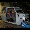
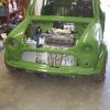
finally fitted and bolted the cage in:
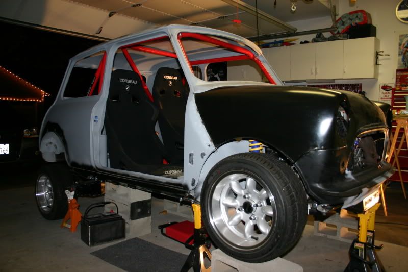
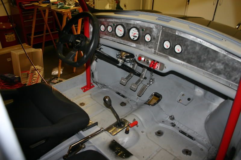
shot of the interior:
another overall shot:
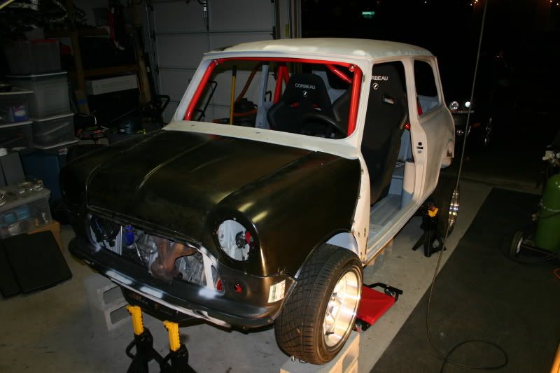
and a head on shot:
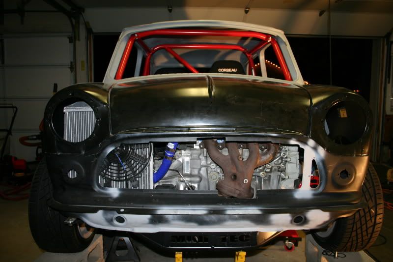
seats are in the process of being mounted, as they are turning out to be much more difficult to install then i expected. got some hood pins and dzus fasteners so the next step after the seats are done is to make the front flip, as right now it's just tacked in place.
finally fitted and bolted the cage in:
shot of the interior:
another overall shot:
and a head on shot:
seats are in the process of being mounted, as they are turning out to be much more difficult to install then i expected. got some hood pins and dzus fasteners so the next step after the seats are done is to make the front flip, as right now it's just tacked in place.


1 user(s) are reading this topic
0 members, 1 guests, 0 anonymous users


