Jump to content


Photo
- - - - -

73 fast road mini


  • Please log in to reply
305 replies to this topic

#61 Chris C

Chris C

    Mini Mad

  • Members
  • PipPipPipPip
  • 212 posts

Posted 09 February 2008 - 07:47 AM

been working on getting the front end together, i have a habit of jumping around from item to item... and nothing ever seems to get done


anyways, the closure panel turned out pretty much just like i wanted, which is good. also cleaned up around the scuttle and a few other areas, still need a little bit of work but already look much better:

Posted Image

and with the front wing clamped in place:

Posted Image

I cut the seam off where it would normally weld to the a panel, since i left the old one on from the original front wing. with the trim strip on, the metal front should slip nicely in a 2 millimeter gap or so in between the trim strip and the closure panel, looking real nice and smooth. I am definitely pleased with the way this all turned out, and the other side is essentially identical. The front panel needs a bit of trimming to clear the exhaust manifold, radiator, and the bottom of the subframe, but nothing all that major. front end should be flipping in no time!

#62 Chris C

Chris C

    Mini Mad

  • Members
  • PipPipPipPip
  • 212 posts

Posted 22 February 2008 - 06:58 AM

UPDATES

did some smoothing and notched the front panel a little bit to fit around the frontmost tube of the subframe, I am really really happy with how it turned out.
Posted Image

Intake manifold is almost finished, credit goes to my dad for all that hard work
Posted Image

Also extended the rear subframe to fit around the tank which is going to be set in the floor similar to how the batter box is. its also now a crash barrier of sorts, since it is relatively think box section. had my friends brandon and justin TIG it all together.
Posted Image

detail of the way overbuilt corners
Posted Image

Oh and i almost forgot, i can roll it around again. sort of cobbled together, but i wanted to just see it on its wheels for once, its the first time since like the summer or something like that.
Posted Image

and that front is LOW. with almost no preload that front bar would be about 2 or 3 inches off the ground.
Posted Image

#63 Bungle

Bungle

    Original Spamster

  • Members
  • PipPipPipPipPipPipPipPipPipPipPip
  • 28,971 posts
  • Location: Cornwall
  • Local Club: cornish mini club

Posted 22 February 2008 - 07:14 AM

nice work :D

#64 panelbeaterpeter

panelbeaterpeter

    Crazy About Mini's

  • Members
  • PipPipPipPipPipPipPipPipPipPip
  • 5,606 posts
  • Location: Scotland
  • Local Club: n/a

Posted 22 February 2008 - 04:12 PM

Wow nice project! good to see things being done properly.

#65 Chris C

Chris C

    Mini Mad

  • Members
  • PipPipPipPip
  • 212 posts

Posted 22 February 2008 - 11:10 PM

yeah, the better i have gotten at doing this sort of stuff the more I hate how all of the early repairs i did turned out. Where I replaced the right side of the boot floor i lined the subframe mount up wrong, and even though I can just go at it with a die grinder I think I am just going to rebuild the entire mount, because I think right now it just looks like complete poo, in lack of a better term. Plan on working on the boot today, get upping the floor to 18 guage, which is always mor fun to work with. Hopefully some progress pictures tonight.

#66 *DJH*

*DJH*

    Up Into Fourth

  • Members
  • PipPipPipPipPipPipPipPipPip
  • 4,972 posts
  • Location: East Anglia
  • Local Club: www.bigpower.co.uk

Posted 27 February 2008 - 04:49 PM

Great looking project :)

#67 romblu89

romblu89

    Mini Mad

  • Noobies
  • PipPipPipPip
  • 105 posts
  • Location: Lux

Posted 07 March 2008 - 08:17 PM

i know it might sound a stupid question....but whats different in your pedal box???

Edited by romblu89, 07 March 2008 - 08:18 PM.


#68 Chris C

Chris C

    Mini Mad

  • Members
  • PipPipPipPip
  • 212 posts

Posted 08 March 2008 - 08:19 PM

In effect it replaces the entire mini pedal assembly, from pedals to the master cylinders. It just bolts up in place on a mount lasercut from minitec that uses the standard mounts for that triangular prism pedal-mount jawn that the stock mini system has, and instead of having the master cylinders be up on the other side of the firewall, they are mounted on top of the pedal assembly on the inside of the cabin. Another thing about them is that it is separated into 3 isolated circuits via separate master cylinders for each of the 3 circuits: clutch, front brakes, rear brakes. total control.

Posted Image

the 2 pedals/3 master cylinder one on the right is what is equipped in my vehicle. Another advantage is that it gives you options as to where you can put the resevoirs, as you can see in the picture they can either be remote mounted (center, 1 pedal) or directly mounted on top of the master cylinder (right/left ones)

#69 romblu89

romblu89

    Mini Mad

  • Noobies
  • PipPipPipPip
  • 105 posts
  • Location: Lux

Posted 09 March 2008 - 10:48 AM

In effect it replaces the entire mini pedal assembly, from pedals to the master cylinders. It just bolts up in place on a mount lasercut from minitec that uses the standard mounts for that triangular prism pedal-mount jawn that the stock mini system has, and instead of having the master cylinders be up on the other side of the firewall, they are mounted on top of the pedal assembly on the inside of the cabin. Another thing about them is that it is separated into 3 isolated circuits via separate master cylinders for each of the 3 circuits: clutch, front brakes, rear brakes. total control.

Posted Image

the 2 pedals/3 master cylinder one on the right is what is equipped in my vehicle. Another advantage is that it gives you options as to where you can put the resevoirs, as you can see in the picture they can either be remote mounted (center, 1 pedal) or directly mounted on top of the master cylinder (right/left ones)


did you use it to maximize space in your engine bay? or so that you can control the front and rear brakes indipendently?

#70 romblu89

romblu89

    Mini Mad

  • Noobies
  • PipPipPipPip
  • 105 posts
  • Location: Lux

Posted 09 March 2008 - 10:49 AM

aaa sorry...didn't notice that there's one pedal and 2 circuits to it...hehe.....really like it....thanks for the info

#71 Chris C

Chris C

    Mini Mad

  • Members
  • PipPipPipPip
  • 212 posts

Posted 09 March 2008 - 04:36 PM

yeah no problem, the car was an auto so i would have had to buy a clutch pedal and master cylinder anyways and just decided to take the plunge instead and go with the tilton setup. It's wayyyyy overkill, especially when you actually hold it and your hand and look at it.

Actually got dirty this weeekend and worked on that trunk floor. i know i keep promising pictures updates and they come like 2 weeks later, but by tonight I ASSURE you all I will have more pictures of the trunk, in case someone else wants to attempt it

#72 Chris C

Chris C

    Mini Mad

  • Members
  • PipPipPipPip
  • 212 posts

Posted 10 March 2008 - 04:01 PM

ok now! step by step guide to reshaping your boot floor to accept a fuel cell!

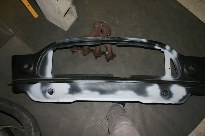
Step 1: cut out spare tire holer and battery box. depending on the size of the tank, you may need to extend the rear bar of the subframe.

Posted Image

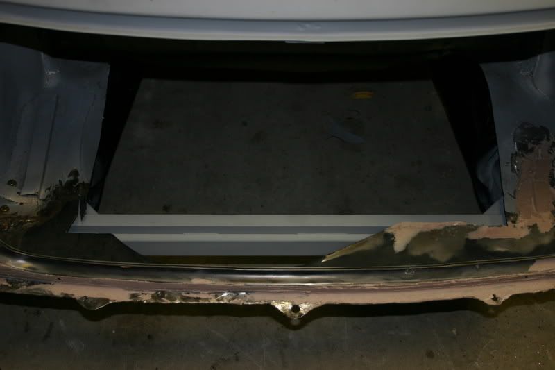
Step 2: cut sheet metal piece slightly bigger then the hole you made. bend to get a real basic curve that is somewhat similar to the way the edges of the boot sort of swoop up and back down to clear the subframe. you can use your knee for this and a deadblow hammer, it really isn't that hard. push sheetmetal back so it jams between the edge of the floor and the back seat, and tack it in. put weight on the panel as it you tack it to the general shape. at this point it is still an overlap joint so it should overlap the original floor about an inch or so on almost all sides. Picture was takedn a bit later so that is why some of the seams are welded.

Posted Image

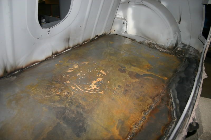
Step 3: after it is al tacked, go around the edge of the panel you made and cut the trunk floor right where it intersects the new panel. go in about 2 inch sections and re-tack the butt joint so it remains the same shape. do this all the way around until it is now just all butt joints. seam weld.

Posted Image

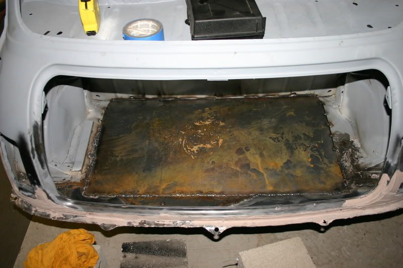
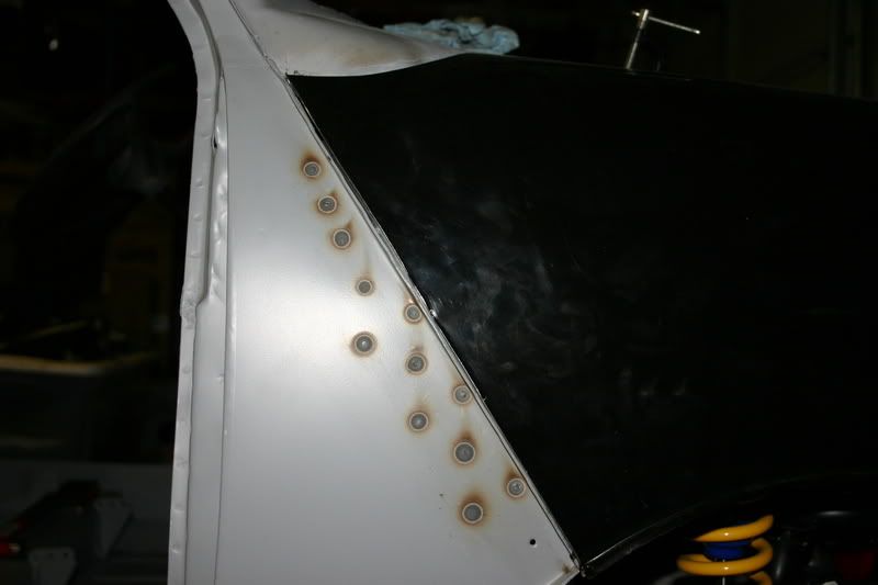
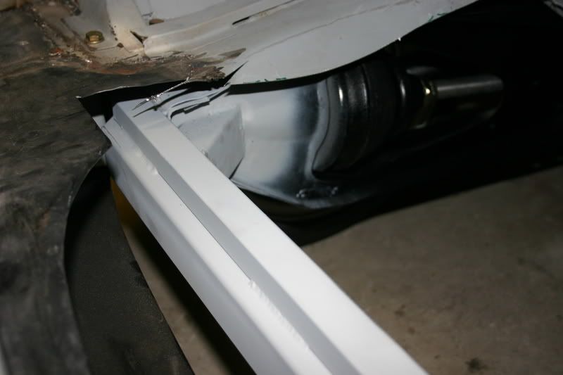
Step 4: for the joint where the panel meets the rear seat, there is this strange sort of downwardnotch that runs most of the length of the panel. cut the panel as close as you can and weld it to the back seat. grind it and it should look like this:

Posted Image

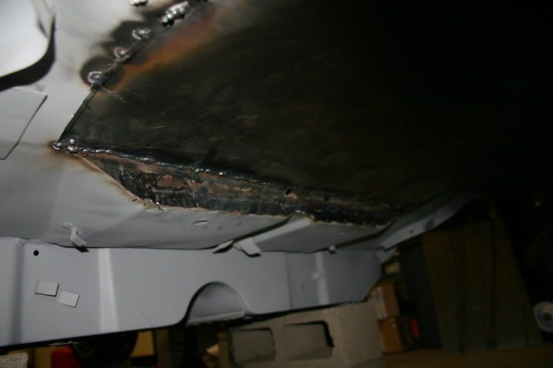
in that picture you can see where the new panel just goes straight across, the seat back is flat the whole height so it is just easier. also, i welded the frontmost seam to the backseat from underneat, as inside with the angle it would be hard to weld and almost impossible to grind. so i went from underneath.

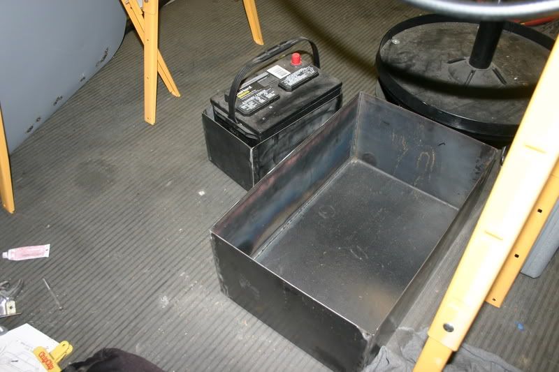
Step 5: Prepare boxes that are the right dimensions for the battery and the fuel cell. make them about 2 inches taller then they should be, for reasons i will get to later.

Posted Image

TO BE CONTINUED

~~~~~~~~~~~~~~~~~~~~~~~~~~~~~~~~~~~~~~~~~~~~~~~~~~~~~~~~~~

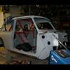
also, got my steering wheel and guages. the wheel was one of the only all black wheels i could find for a decent price, and while the shape of the wheel is very nice the plastic feel is dissapointing. I think will just trim it with black leather at some point. The guages are all autometer, phantom series.

Posted Image

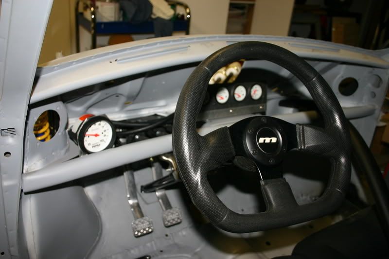
everything is in a temporary setup at the moment, that is just how they are mounted for startup.

#73 Ferrina1275

Ferrina1275

    Stage One Kit Fitted

  • Noobies
  • PipPipPip
  • 86 posts

Posted 14 March 2008 - 07:53 PM

Hey fella, that's really coming together nicely, good job! I love those SOHC engines, I've had two Civic's in the past and they really fly. God only knows how it will perform with 400kg less to cart around!! 130bhp is plenty of power to play with, plus you can turbo it in the future to 200+bhp. Possibly looking to do a Honda conversion on my next project car... but I'll stick with reverse engineering my car for now!!!

Edited by Ferrina1275, 14 March 2008 - 07:55 PM.


#74 Monte Busa

Monte Busa

    Super Mini Mad

  • Noobies
  • PipPipPipPipPipPip
  • 681 posts
  • Location: Michigan, USA

Posted 14 March 2008 - 08:08 PM

Chris,

What are the length and width dimensions on that flat plat you welded into your boot?

Posted Image


#75 Chris C

Chris C

    Mini Mad

  • Members
  • PipPipPipPip
  • 212 posts

Posted 16 March 2008 - 06:07 AM

Ferrina1275:
Thanks, it should destroy tires very nicely. And a 1275 in a Smart? I could ask why but then again people seem to ask me that all the time as well, haha.


Monte Busa:

It was 32 inches by 19 inches when it was flat, so the hole I cut in the boot floor is slightly smaller then that. Of course that isn’t really exact, as both the boot floor and my cuts on the new panel aren’t exact. There is probably over a quarter inch variance in some places. The little moon-shaped panel at the bottom is just 20 gauge that I welded in in order to make it so that my 18 gauge panel could be completely rectangular. I pretty much tried to remove any sort of shape that the boot floor had, besides the gentile curve that runs along the sides to clear the subframe.


0 user(s) are reading this topic

0 members, 0 guests, 0 anonymous users