Jump to content


Photo
- - - - -

Kws's Mini 1000

roundnose

  • Please log in to reply
88 replies to this topic

#16 kws

kws

    Stage One Kit Fitted

  • Noobies
  • PipPipPip
  • 63 posts
  • Location: Wellington, New Zealand

Posted 20 June 2018 - 09:49 AM

I bet these days half the inspectors wouldnt know what they were looking at on a Mini anyway  :lol:


I have a good WOF guy, but he cant do re-registration, so I have to play by the books until i pass that, and then ill have some leniency.


#17 kws

kws

    Stage One Kit Fitted

  • Noobies
  • PipPipPip
  • 63 posts
  • Location: Wellington, New Zealand

Posted 21 June 2018 - 08:05 AM

The first thing to check in order to fix the misfire, was the ignition system.
 
The obvious place to start was the ignition leads. I have replacements on the way, but in the mean time I needed to try to insulate the existing ones. Electricity/Spark has a great habit of taking the path of least resistance, so if it is easier for the spark to go anywhere BUT the spark plug, that's where it will go.
IMG_1725.jpg
 
The previous owner kindly left three of the four boots on the dash, so I greased them up and slipped the boots on. The lead that I didn't have a boot for I tried to insulate with insulation tape. These leads are only temporary.
IMG_1813.jpg
 
I also checked the spark plugs. They don't look too bad, but the gap was massive. They were all over 1.1mm, so I gapped them down to the commonly used 0.8mm (manual calls for 0.6mm but that is crazy small). Plugs One, Two and Four were all the same colour as below, but plug three was dark and a little sooty.
IMG_1814.jpg
IMG_1765.jpg
 
After refitting the gapped plugs I checked the cap and rotor. The rotor was looking a bit average, and strangely had over spray on it
IMG_1815.jpg
 
I gave it a quick touch up with some fine sandpaper to clean the tip and the center contact point
IMG_1817.jpg
 
The cap though, is well past it. There were a lot of deposits on the terminals, and the terminals are badly pitted. I cleaned as much as I could off the terminals, but they aren't going to be helping anything.
IMG_1816.jpg
 
I'll order a distributor service kit, to replace the cap, rotor, condenser and points.
 
I took it for a test drive after this little service, and already there is a noticeable difference. The misfiring has lessened a lot, and it runs smoother. It still isn't idling perfectly, and the misfire is still there, so I still have some work to do. The exhaust leak wont be helping and I bet the carb is filthy.


#18 kws

kws

    Stage One Kit Fitted

  • Noobies
  • PipPipPip
  • 63 posts
  • Location: Wellington, New Zealand

Posted 25 June 2018 - 11:21 AM

Well, I'm not kidding, I'm all over the place with the Mini at the moment.
 
Most of the work I'm doing now is waiting on parts, so I start a job, get to needing parts and then move onto the next job. Rinse and repeat.
 
I was about to say "but wait, there was one job I completed!" but then I realised I didn't. Sad face. This job was the first one I did yesterday; greasing my nipples.
 
I started with the best of intentions, having purchased a fancy new "brand name" grease gun and watching some YouTube videos on the task. There are four grease points per side, three in the front, one at the rear. I started with the rear one as it's really easy to get to. I gave it a quick clean
DSC02767.jpg
 
On went the grease hose, and after a few pumps I spotted grease coming out the other end of the arm (this is good, it's your indicator to stop)
DSC02773.jpg
DSC02774.jpg
 
Unfortunately this is about where the fancy pants grease gun gave up and I had to go exchange it for a "store brand" gun, which by the way, worked perfect.
 
The front ones require the car to be jacked up at the front, but you don't need to remove the wheels. These are the grease nipples, handily pointed at by the nozzle of my brake clean can
DSC02775.jpg
DSC02776.jpg 
DSC02777.jpg
 
Much more obvious after a clean
DSC02778.jpg
DSC02779.jpg
 
Once again, pump in grease until you can start to see it coming out. Here it is coming out of the lower joint boot
DSC02780.jpg
 
Unfortunately as you can notice in the above photos, the top ball joint grease nipple on both sides of damaged, and just leaks grease. I'll order new nipples and fit them. So that was the first job that is half done.
 
Moving on, the next thing on the list was to redo the sump plug, which was leaking a fairly significant amount of oil since I replaced it. I knew this was a risk, but its kinda my own fault for using the original copper washer and liquid thread sealer when the thread wasn't perfectly clean. Argh.
 
I drained the oil again. There goes $60 of oil with less than 5KM on it.
DSC02781.jpg
 
This time I used proper thread tape, and a genuine Rover copper crush washer. This type of washer is standard for what is used on my SD1, it's a copper washer but is designed to crush and seal when tightened. This type of washer can account for slight variations in the surface (ie: tapping the thread on an angle >_< 
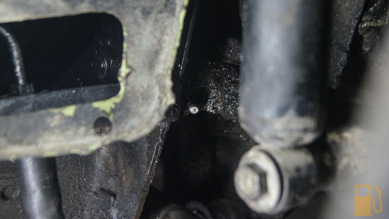
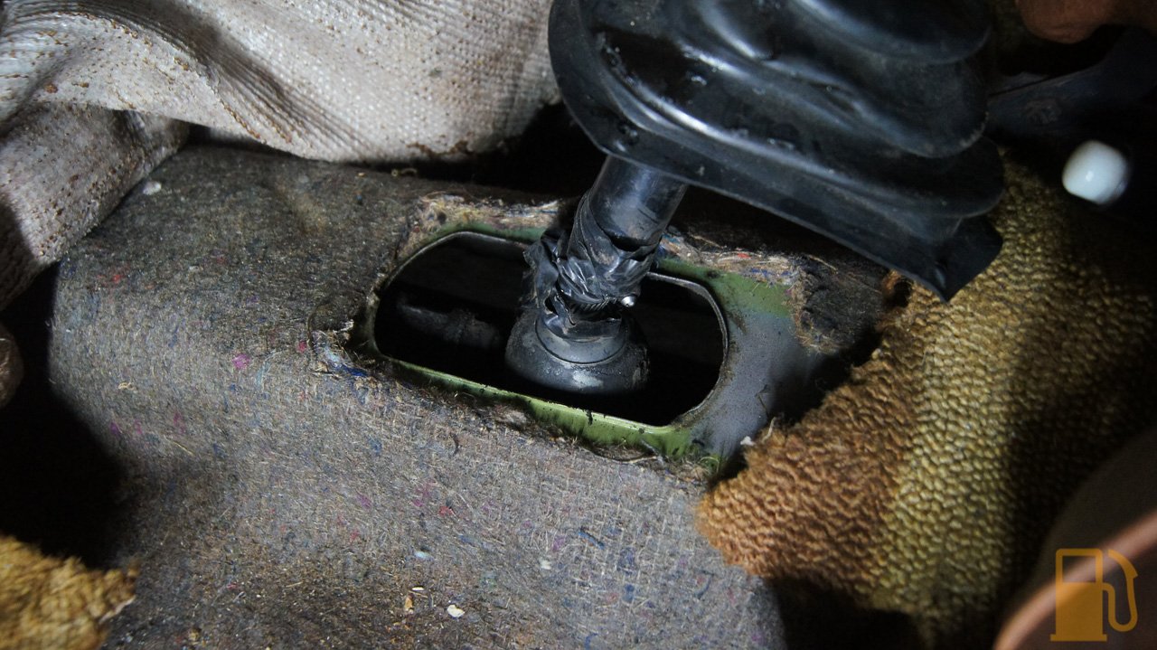
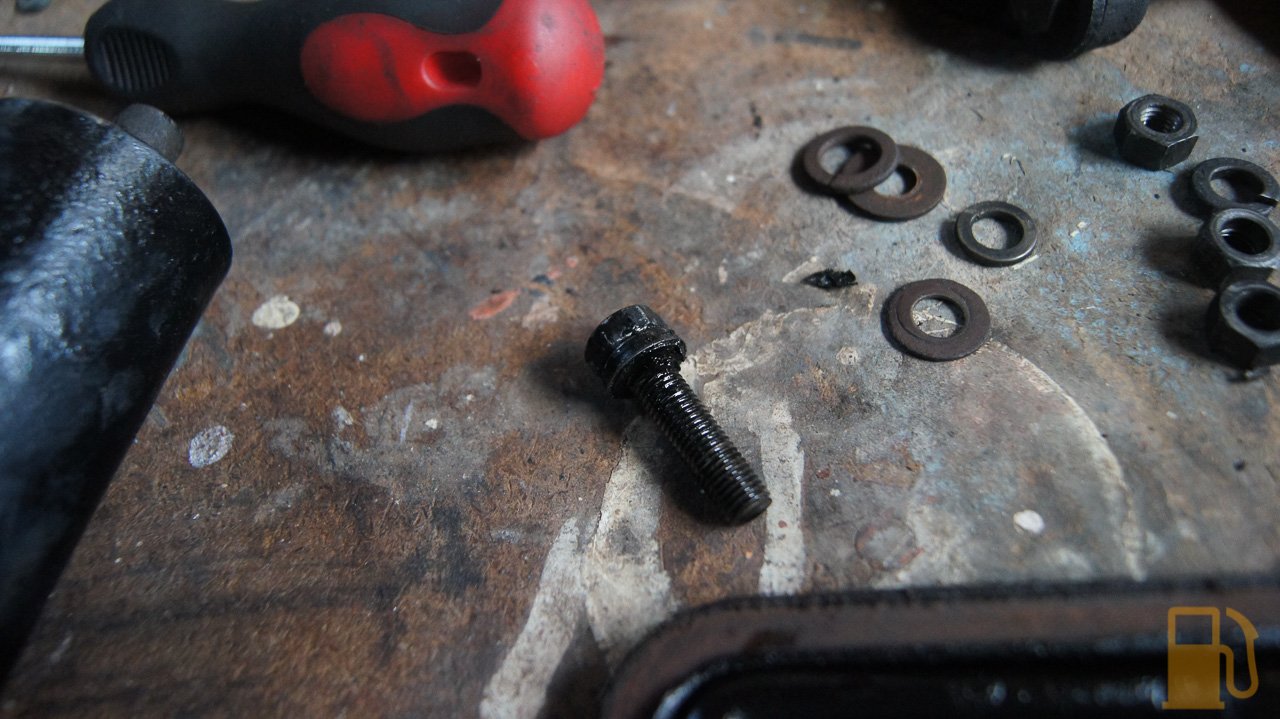
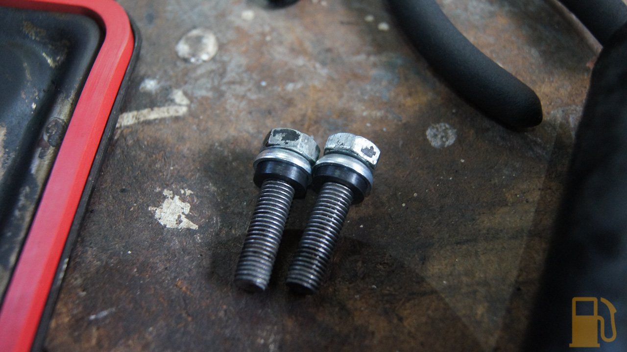
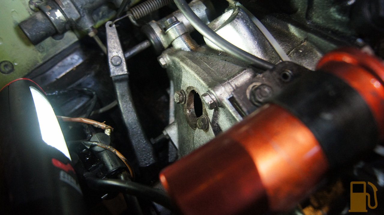
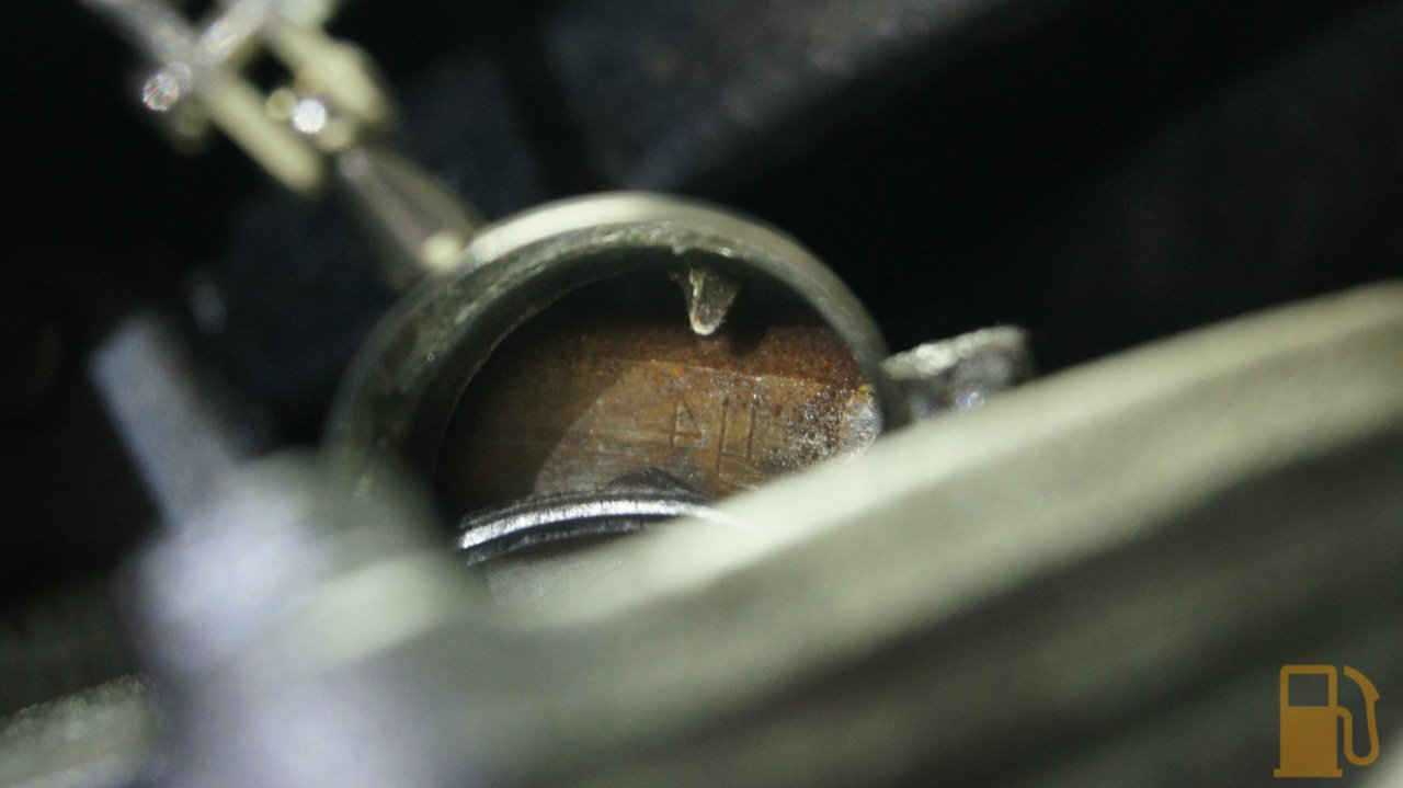
). I also made sure that the threads in the gearbox were 100% clean and dry before fitting
DSC02791.jpg
 
I don't have much spare oil, so used the left over 400ML I had. So far there has been no sign of any weeping. I left it overnight with a white rag under it, and it was still clean the next day.
DSC02800.jpg
 
I can't fill the engine with oil until I have done the selector oil seal, which is currently leaking. The parts are on the way for that.
 
Next on the hit list was another serious oil leak that I had noticed. It was from the back of the engine, so either fuel pump gaskets or timing chest gaskets. Both of these gaskets are on order, but in the mean time I needed to gain access to the back of the engine. Access is blocked from the underside by the diff, and blocked by the manifold/exhaust/carb on the top. I needed to remove the manifold and carb as the exhaust was leaking and the carb needed a clean, so off it came.
DSC02782.jpg
 
The carb is easy to remove, just two nuts and various hoses and cables
DSC02783.jpg
 
Whilst there I couldn't help but pull as much of that matting out from behind the master cylinders. It had soaked up various fluids and gone really gross
DSC02784.jpg
 
The manifold it self comes out as one unit. The clamp from the manifold to downpipe was a real pain to get off. For some reason it was seized on one side and required a lot of BFH percussive persuasion.
DSC02786.jpg 
 
Plenty of space down the back now.
DSC02789.jpg
 
The carb was dirty but didn't appear too bad. I wanted to strip it down and inspect/clean just to know what I had.
DSC02790.jpg
 
I don't know what oil was in the dashpot, but jeez it was hard to raise the piston by hand. It was super thick.
DSC02792.jpg
 
The breather inlet on the carb was blocked, but the hose clamp was loose. Wouldn't be helping. I'll be reinstating the proper breather setup upon reassembly.
DSC02793.jpg
 
I removed the dashpot and piston. There was a bit of filth inside the carb and on the piston. Not much wear though
DSC02794.jpg
DSC02795.jpg
DSC02796.jpg
  
The float bowl had some muck in the bottom, but the fuel in it was clean
DSC02797.jpg
 
I gave the carb a thorough clean inside and out. The needle came out to check what needle was fitted, ADE, and give it and its fittings a good clean. Someone had been here before, and overtightened the screw that holds the needle in place and cracked the holder. It's OK for now, but will try to source a replacement when I uprate the needle.
DSC02806.jpg
 
Whilst poking around and cleaning the body of the carb I found the piston lift pin. This is what you use to lift the piston and check the mixture
DSC02807.jpg
 
Piston UP and DOWN
DSC02808.jpg
DSC02809.jpg
 
I started to reassemble, and gave the dashpot cover a quick clean and polish. I don't want it too shiny but a rub down with a scuffing pad made it look OK
DSC02810.jpg
DSC02811.jpg
 
I had to stop there though as I need my float chamber gasket to arrive. Next on the bench was the manifold. I needed to clean the gasket goop off the flange and downpipe connection. Of note, there was no exhaust paste on the manifold or downpipe.
DSC02812.jpg
DSC02814.jpg
 
The gasket was well past its best, no wonder so much sealant was used
DSC02813.jpg
 
Some good scraping and wire brushing got the flange looking nice
DSC02816.jpg
 
It's so tiny! I look forward to fitting the much bigger Long Center Branch headers in the future
DSC02817.jpg
 
Now I need to wait for all my gaskets to arrive, and then I can fit all that back together.
 
In the mean time, I had a fiddle under the bonnet. I have an overhaul kit coming for the carb, with new cap, rotor, points and condenser, but in the mean time I wanted to see what the gap was like on the old points. The gap was a lot smaller than the required 0.30-0.40mm gap. I adjusted them to the correct gap just to test that I still remember how to do it, after so many years.
DSC02821.jpg
 
But hey, I'm not done there either! So, next was to move inside and the car and make a mess there.
 
I wanted to know what the random wires, and random button on the steering column was. So I went on the hunt.
IMG_1757.jpg
 
A couple of screws, and here's what its connected to.
DSC02826.jpg
 
Nothing.
 
So where does the green wire hanging under the dash go?
DSC02827.jpg
DSC02828.jpg
 
Turns out its wired direct to the ignition switch. Switched live then I guess. That got removed.


#19 kws

kws

    Stage One Kit Fitted

  • Noobies
  • PipPipPip
  • 63 posts
  • Location: Wellington, New Zealand

Posted 25 June 2018 - 11:22 AM

I also removed a large speaker wire that runs from the boot to the front of the car, and connects to nothing. I think its connected to the reverse lights, so that might have something to do with my next weird find....
DSC02830.jpg
 
Lots of tape, a hose clamp, and a microswitch.
DSC02831.jpg
 
Not hooked up to anything mind you. I removed the shifter to remove all that rubbish, and also lubricated the moving parts.
 
Whilst in the interior, out came the seats
DSC02832.jpg
 
This wasn't just random. Both of the seats have busted diaphragms under them, so you fall through the passenger's seat and the driver's seat is reinforced with a couple of slabs of wood
IMG_1812.jpg
 
I have new, updated sprung mesh diaphragms on their way from Minispares, so have to have the seats out for that. The other major issue I needed them out for was to weld the floor.
 
Weld the floor? No, not because of rust, because of someone using too much brute force on the hand brake.
DSC02833.jpg
DSC02835.jpg
DSC02836.jpg
  
I noticed this the other day because I need to adjust the hand brake, as it barely holds the car (and wouldn't pass inspection). Unfortunately someone had known this, so had been there and wound the adjuster full to its stop. After some more BFH work, and careful levering I had the mounts back roughly where they should be. You can see how far away the clevis under the mount is from the hole it should attach to
DSC02842.jpg
 
I placed the lever where it should sit and then wound out the adjuster. Well I guess I have my adjustment back!
DSC02845.jpg
 
Now I need to crack out my new welder and zap some metal back into the front mount to attach it to the floor.
 
Speaking of floor, look at that lovely untouched metal.
DSC02843.jpg
 
Since I couldn't be bothered getting the welder out at this very moment, I moved onto removing the dash gauges. I need access to the back of the oil pressure gauge, as I have a replacement oil supply hose on the way, since the old one leaked badly and the seller crimped it off. I needed to remove the badly warped dash cover first. Two screws got the whole lot out. Not sure what to do here, the old one is so warped I don't really want to fit it again. Will look at options.
DSC02851.jpg
 
I found these two gems stuck behind the dash cover. A card from the Canterbury Morris Minor Club, and an old ice scraper card.
DSC02849.jpg
 
The central gauges are easy to get out, with just a few screws to remove
DSC02852.jpg
 
Since the gauges were out, and I felt like I needed something else to do, I removed and cleaned the oil pressure gauge.
DSC02854.jpg
DSC02855.jpg
 
The same scuffing pad I used on the dashpot cover was used on the chrome ring with good results. I also thoroughly cleaned the glass
DSC02856.jpg
DSC02857.jpg
 
The temperature gauge had a weird hazing on the inside of the glass, around the edge
DSC02865.jpg
 
I chose to strip this gauge and clean the inside of the glass. Using some brute force I twisted the bezel to line up the tabs and allow it to be removed
DSC02866.jpg
DSC02867.jpg
 
A thorough polish and clean, and BAM, mint (well, kinda, this photo was before I polished the bezel)
DSC02869.jpg
 
The speedo was next in the hit list. Heres a half-half shot of polishing the chrome
DSC02871.jpg
 
and all reassembled. Blingin'
DSC02877.jpg
 
But wait, there's more!
 
I found a weird random wire chilling in the engine bay. Turns out it was the purple/orange wire I was looking for (I thought it was brown/orange, but couldn't find it on the wiring diagram). Its meant to connect to the inline fuse behind the gauge cluster (the black thing to the left of the wire)
DSC02802.jpg
 
Unfortunately there was no spare wire on the other side of the fuse holder for me to join to, so I chose to replace the holder with a more modern blade fuse holder. Not my neatest work, I may tidy it up later, but it should do the job.
DSC02804.jpg
 
Just a quick note, when replacing a glass fuse with a blade fuse the rule of thumb is to halve the rating of the glass fuse. It's a long story, but something to do with slow and fast blow.
 
So what does it do? Well, this!
IMG_1827.jpg
 
Which I changed to a warm white LED
IMG_1828.jpg
 
Oh, and this. Hazard lights!
IMG_1829.jpg
IMG_1830.jpg
 
Great success. I guess that's one job I actually finished. Nope, damn, I need a spare flasher relay.
 
So yeah, lots of unfinished jobs. Lots of bits everywhere. Lots of waiting on parts. Thankfully the parts will be here this week. I also need to weld the hand brake mount, so will get onto that soon.
 
Then jeez, I might almost be ready for the rego inspection. Maybe.


#20 kws

kws

    Stage One Kit Fitted

  • Noobies
  • PipPipPip
  • 63 posts
  • Location: Wellington, New Zealand

Posted 27 June 2018 - 12:32 PM
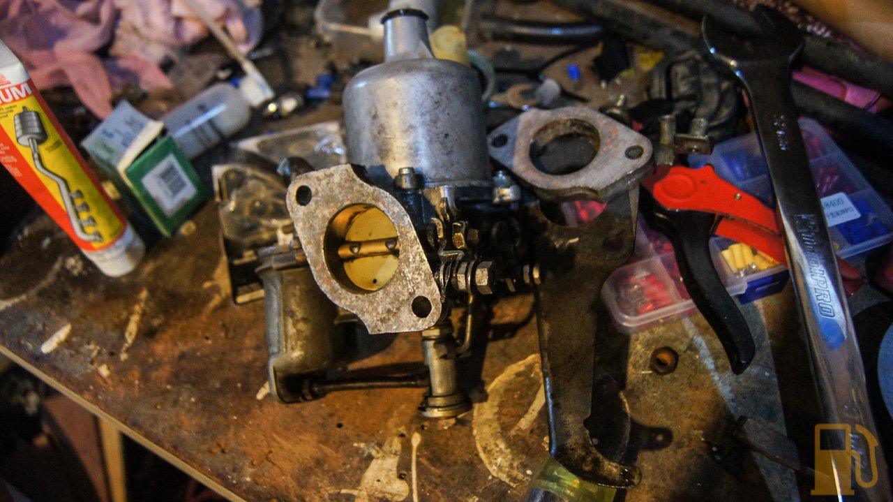
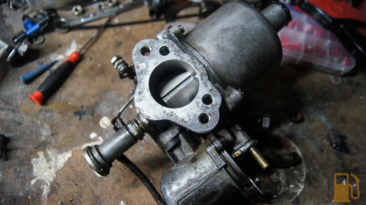
Parts arrived! Woooo!
 
Theres nothing like a big box of parts, and it was certainly a big box
DSC02878.jpg
 
I do love getting new parts, but this also means I can finally start the reassembly of the Mini.
 
The first task was to finish reassembling the carb. The float bowl gasket went on first
J4912x2760-00002.jpg
J4912x2760-00003.jpg
 
and then I realised I forgot to order a gasket for the inlet of the carb. Oops. This is why I have a sheet of gasket paper though, so I traced the old gasket and made a new one. I fitted the gasket with a thin smear of sealant on each side, just to be sure it seals OK.
J4912x2760-00004.jpg
J4912x2760-00005.jpg
J4912x2760-00006.jpg
  
Now, before refitting the manifold and carb, I needed to deal with the two potential areas of oil leaks on the back of the engine. First was the tappet chest covers. These are both held on with a single bolt each, through the middle.
J4912x2760-00008.jpg
 
The gasket was VERY compressed, far more compressed than it should be for the tiny little torque required to fit them. The bolt sealing rubbers were both hard as plastic and shredded, so that wouldn't be helping.
J4912x2760-00010.jpg
J4912x2760-00012.jpg
 
The plate with the breather on it had a pinched and twisted gasket, and clear signs of oil leaking through the gasket
J4912x2760-00013.jpg
J4912x2760-00014.jpg
J4912x2760-00015.jpg
  
I thoroughly cleaned and flushed the breather out with brake clean until it ran clear, and then cleaned the covers and fitted new gaskets.
J4912x2760-00016.jpg
J4912x2760-00018.jpg
J4912x2760-00017.jpg
  
I wanted to make sure these were fitted at the correct torque, so that the gaskets didn't get crushed. I have a little digital torque wrench thing for jobs like this, so put it to good use. The Torque setting in the book is about 4.7NM, but I chose to round it up to a nice even 5NM.
J4912x2760-00019.jpg
 
And on they went
J4912x2760-00020.jpg
 
The next potential source of an oil leak was the mechanical fuel pump. Two nuts, and a hose clamp saw that removed. I dare say this may have been the cause of the main leak, as there was no gasket fitted between the spacer and the fuel pump, and the sealant really had not worked as expected.
J4912x2760-00021.jpg
 
I thoroughly cleaned the pump and spacer, and using a small smear of sealant fit a gasket to each side of the spacer
J4912x2760-00023.jpg
J4912x2760-00024.jpg
 
When refitting the outlet pipe though I noticed some worrying cracks in the hoses. I made a quick dash to Supercheap and got some new hose to replace these
J4912x2760-00026.jpg
J4912x2760-00027.jpg
 
With those sorted it was time to refit the cleaned up manifold. I slipped a new gasket on the studs
J4912x2760-00032.jpg
 
Smeared a small amount of exhaust sealant on the exhaust flanges (there was some slight pitting, so wanted to make sure the gasket had the best chance of sealing), slathered sealant on the downpipe flange
J4912x2760-00030.jpg
J4912x2760-00031.jpg
 
And carefully refitted the manifold, torquing the nuts correctly as I went. I'll tell you what though, refitting the downpipe to manifold clamp was a real pain.
J4912x2760-00033.jpg
 
On went the freshly cleaned carb, with its gasket sandwich and spacer. Also note the fuel filter, which was soon removed. I just couldn't get the fuel pipe to line up nicely with the filter on there, and the pipe kept contacting the exhaust, which is no good. I may fit it under the car on the tank outlet instead.
J4912x2760-00034.jpg
 
Here it is with the fuel plumbed back up normally, and the reinstated breather (using old and useless for fuel, fuel hose). I know the heater hose "adaptor" to the breather isn't the best, but hell, why does it step up so much from one end of the hose to the other? Silly BLMC.
J4912x2760-00035.jpg
 
With the inlet and exhaust sorted, I moved to the next little task to do. Refreshing the ignition system. I'm not a huge fan of points, but they will do the job for now. The old ones were showing signs of pitting, so they needed to go
J4912x2760-00036.jpg
 
I have new points, condenser, rotor and cap
J4912x2760-00039.jpg
 
Replacing the points and condenser is easy, it's literally two screws and then setting the points to the correct gap. I'm glad to see someone has greased and oiled the distributor somewhat recently too.
J4912x2760-00040.jpg
J4912x2760-00041.jpg
 
There it is, all ready for its new leads. They will need to wait a little though, as the spark plugs are currently out so that I can easily rotate the engine for other work.
 
With more new parts to fit, I kept cracking on. Next up was a new throttle cable, as the old yellow one that can be seen in some previous photos, was knackered. It still worked, but the outer sleeve was broken in multiple places. To replace the cable I unbolted the throttle pedal from the floor, as its only two bolts. Interestingly there was another random wire attached to one of the studs. This wire, like the rest, went nowhere.
J4912x2760-00042.jpg
 
I did find what I think are my actual reverse light wires though, tucked up under the dash behind the carpet. I'll need to test these, and hook them up again at some point. I'm getting pretty close to everything actually working on this little car. Pretty impressive considering a couple of weeks ago nothing worked... oh, and Lucas.
J4912x2760-00043.jpg
 
The new throttle cable was a piece of cake to fit. It made a nice difference to the engine bay visuals, not having that ugly yellow thing running across the engine. Spot the new cable.
J4912x2760-00045.jpg
 
The final job for the day was to remove the old, warped rocker cover, and check the valve clearances.
J4912x2760-00046.jpg
 
Stevestonmotorco on YouTube has a great video on how to set the valve clearances, using the Rule of Nines. The Rule of Nines means that you look at which valve is completely open, and then use what ever other valve combined with the open one equals nine. So for example, if valve 8 was completely open (the valve spring is fully compressed) then you would adjust valve number 1, as 8 + 1 = 9. 5 (Open) + 4 (Adjust) = 9 and so on.
 
Because you need to turn the engine over to open and close valves, you will need to remove the spark plugs to make it easier (not fighting compression). I also found that if you jack one side of the car up just enough to get a front wheel off the ground (I jacked up the LH front wheel), put the car in 4th gear, you can easily turn the engine over by hand by turning the wheel. Because of how small the Mini is, you can even turn the wheel whilst still sitting at the front of the car.
J4912x2760-00050.jpg
 
In the interests of knowing the car, and how well it hasn't been maintained, I took note of each valve clearance before I adjusted them. The results were... interesting.
 
Valve clearances should be set to "12 thou", or 0.012"/0.30mm. These are the results I obtained (ignore the missing zeros in the figures on paper)
J4912x2760-00047.jpg
 
Cylinders 1,2,5,7 and 8 were all about 0.009". Cylinder 3 was 0.007". Cylinders 4 and 6 were LESS THAN 0.006", but I didn't have a smaller feeler gauge than that.
 
Needless to say it wasn't good. I'm glad I checked them. Resetting the clearances is easy on these engines. Loosen off the locknut with a spanner, turn the screw to adjust the clearance with a screwdriver until the correct feeler gauge has a slight drag (with downwards pressure on the screwdriver applied), and then nip the nut back up tight again (whilst holding the screwdriver to stop the screw turning).
J4912x2760-00049.jpg
J4912x2760-00048.jpg
 
I went over all of the cylinders once, and then spun the engine over and then checked them all again. I did note a little more drag than expected from two cylinders, so adjusted them again and its all good. It will be interesting to see how the engine runs now, hopefully it makes a difference. Just need to fit my flash new rocker cover and we'll be sorted there.
 
I still have more work to do on the car, and should have another update in the next day or so. I'm hoping to get the welding on the hand brake out of the way tomorrow and then I can reassemble the interior.


#21 Bat

Bat

    One Carb Or Two?

  • Members
  • PipPipPipPipPipPipPip
  • 903 posts
  • Location: Bermingum

Posted 27 June 2018 - 02:38 PM

Hi,

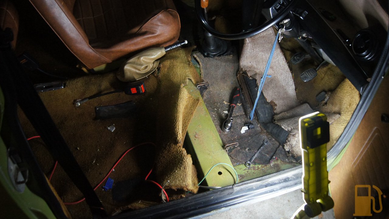
Wow thats a through going over you're giving that mini.

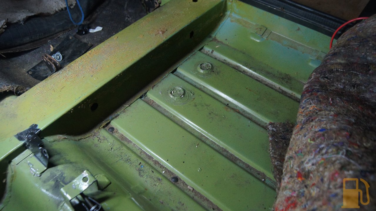
If you were in the UK you'd still be cutting the complete rotten floor out before you could think about doing anything else!

Nice to see a mini in good original condition  :D

Cheers  :proud:


#22 Roach

Roach

    Stage One Kit Fitted

  • TMF+ Member
  • PipPipPip
  • 58 posts
  • Location: BC

Posted 27 June 2018 - 04:24 PM

This is great man! It's so well documented I feel as if I am right there working away.


At this rate she will be running like a champ, keep up the good work! And hello from Canada  :proud:


#23 kws

kws

    Stage One Kit Fitted

  • Noobies
  • PipPipPip
  • 63 posts
  • Location: Wellington, New Zealand

Posted 27 June 2018 - 10:28 PM

Thanks guys. I really do hope it runs like clockwork after all this, but at least if it doesnt its an A series, its not rocket science haha.


Its shocking to me how almost every single project thread here starts with "I purchased this decent looking Mini, now i will cut the front off and remove the floor as its all made of hopes and dreams". You guys really do get the raw deal with salted roads.


#24 timmy850

timmy850

    Up Into Fourth

  • TMF+ Member
  • PipPipPipPipPipPipPipPipPip
  • 2,973 posts
  • Location: NSW, Australia
  • Local Club: MITG

Posted 28 June 2018 - 04:59 AM

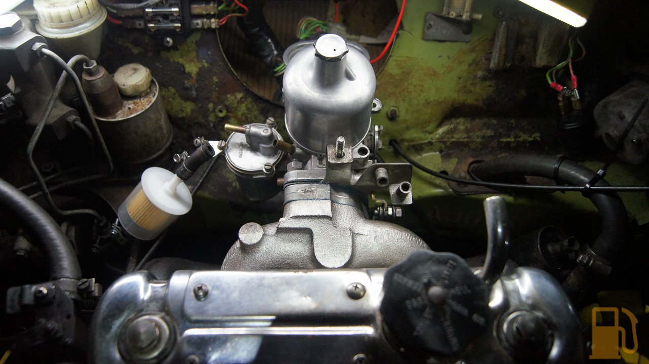
Looking good. In regards to the fuel filter, get a Ryco Z92 or equivalent. They have a 90 degree angle in them, so perfect for going to a SU carb


#25 Bat

Bat

    One Carb Or Two?

  • Members
  • PipPipPipPipPipPipPip
  • 903 posts
  • Location: Bermingum

Posted 28 June 2018 - 08:03 AM

Hi,

I think they built the rust into the cars in this country!

The rumour is they built the bodyshell on the one side of the road and then it went on a conveyor system to the paint shop on the other side of the road uncovered no matter what the weather!

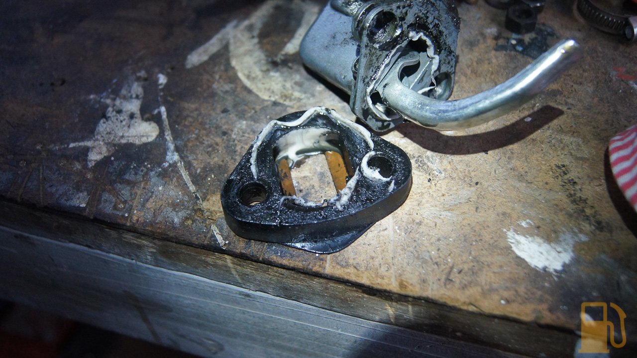
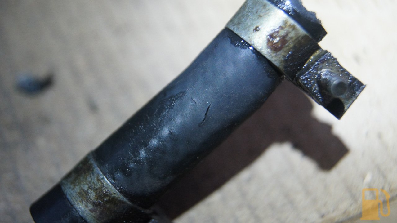
I can't remember if it was on minis or something else but I think there was a plastic bush fitted to the carb to step down the breather pipe so it would be the same size as the breather end along it's length?

Cheers  :proud:


#26 warning634

warning634

    Speeding Along Now

  • TMF+ Member
  • PipPipPipPipPip
  • 488 posts

Posted 28 June 2018 - 08:43 AM

You are doing a great job on this keep it up :proud:


As you are doing a lot of wiring etc I can thoroughly recommend https://www.wiredbyw...roducts-prices/ he has some great products.


Cheers


#27 kws

kws

    Stage One Kit Fitted

  • Noobies
  • PipPipPip
  • 63 posts
  • Location: Wellington, New Zealand

Posted 01 July 2018 - 10:58 AM

No one likes either a saggy unsupportive seat, or one where you literally sit on wood. The Mini had both, and it was time to fix it.
 
 
The first, obvious step, is to remove the seats from the car. In a Mini this is super easy, with just two bolts at the front to remove.
 
Once out, I took the driver's seat into the house and began pulling it apart. This is what I started with. A very hard, unsupportive seat that was bodged with wood.
DSC03012.jpg
 
The diaphragm is the large black rubber part with the holes in it in the above photo. This is used kinda like a big sprung net that allows some support and spring for your bum when the seat is sat in, making the seat comfortable. To replace the diaphragm you need to strip the whole base down. This isn't too hard to do, as long as you're careful.
 
First you need to remove the vinyl cover. This is held to the frame with the black metal clips. These have two little tangs on the top side of them (the side you can't see) that dig into the material and hold them in place. I used a flat blade screwdriver to carefully pop them off. Some were a bit harder to remove, so I used needle nose pliers to gently wiggle the clips free of the material
 DSC03014.jpg
DSC03013.jpg
 
I found this froggy rag stuffed inside the cover of the seat. Not sure if it was added to help bolster it, or just randomly stuffed in. Should make a good rag in the garage.
DSC03015.jpg
 
With the clips removed, gently peel the cover back. Take care that it might be slightly stuck to the pinky-red material wrapped around the base, so carefully peel the cover free
 DSC03017.jpg
DSC03018.jpg
 
If the original diaphragm is as stuffed as mine, and no longer attached to the frame, the foam and diaphragm can be pulled out. If your diaphragm is still attached to the frame you will need to unhook the metal hooks from the frame. My diaphragm was stuck to the foam. I'm not sure if its meant to be stuck to the foam or not, but it was a pain to pull away without damaging the foam.
 DSC03019.jpg
DSC03020.jpg
 
A random chunk of hard rubber was stuffed into the back of the cover. More bodged "fixes".
DSC03021.jpg
 
With the foam off the seat you have access to the top of the frame. This allows you to hook in your new diaphragm hooks or springs. In my case I'm using a newer style diaphragm with springs, and not the rubber. This should hopefully last another 38 years.
DSC03024.jpg
 
This came with instructions which were good to show how to attach the springs, which although isn't hard to do can be a pain the first couple of times. You don't want to get it wrong as the springs are fairly strong. They also have a different type of hook on each end of the spring, the less curved hook goes in the frame.
DSC03022.jpg
DSC03023.jpg 
 
The new diaphragm fitted. One issue I noted was that the front and rear springs are too long for this seat and aren't under tension. They stay in place OK because of the foam, but they can fall out until the foam is in place properly (and it looks like one even fell out before this photo)
DSC03025.jpg
 
One thing I stuffed up first time, and it isn't mentioned in the instructions, is that I didn't slip the loop of vinyl through a spring before fitting to the diaphragm. This loop is at the back of the seat base
DSC03026.jpg
 
I had to strip the foam out again, and remove the two rear springs and slip them through the loop before reattaching.
DSC03028.jpg
 
And the completed diaphragm, with the clips reattached. Unfortunately one of the clips broke in half during assembly, so I'm short one.
DSC03031.jpg
 
The seat isn't back in the car yet, but already its 120% more comfortable. Like a good Mini seat, it has that slight suspension spring when you sit in it. I'll do the passenger's seat tomorrow. That one has no wood in it, so it was almost like sitting on the floor when you fall through the frame.


#28 kws

kws

    Stage One Kit Fitted

  • Noobies
  • PipPipPip
  • 63 posts
  • Location: Wellington, New Zealand

Posted 01 July 2018 - 12:23 PM

As part of the recommissioning process, I chose to replace the bushes for the engine steadies with uprated poly bushes.
 
The Mini runs three steady rods, that run from either the subframe or the body to the engine. These restrict the rocking movement of the engine, and are fairly important to keep in good condition.
 
When I was under the car a while back I noted that one of the lower steadies had badly perished bushes. They run rubber bushes standard, which obviously doesn't play nice with oil leaks and time, both of which this car has had in bucket loads.
IMG_1783.jpg
 
I ordered some uprated, harder poly bushes from Minispares, which arrived the other day.
 
Removal of the steadies is generally simple as anything, just a spanner and ratchet to remove them, remembering which steady went where (although they are different angles so couldn't be swapped anyway). I chose to only do two of the steadies and they seem to be the main ones people focus on, the top steady, and the lower LH steady.
 
The lower steady was first to get sorted. The bushes obviously weren't in the greatest shape
DSC02945.jpg
 
I don't know if its standard or these had been replaced, but they were a two piece bush. I pushed the center pin out with a screwdriver, and then the two halves of the bush just popped out with some leverage.
DSC02947.jpg
 
The new Minispares poly bushes are two piece too, so very easy to fit. No press needed. I used some rubber grease on the bushes to help slip them into the rod, and to in theory, help reduce any squeaking they might make during use.
DSC02949.jpg 
DSC02950.jpg
 
And refitted to the car. Easy.
DSC02952.jpg
 
The upper mount has a couple more things to remove to get it free. The engine side has a mounting plate to remove, and the bolts for that were rather tight. I have heard of them shearing off, so take care, but otherwise it's easy to remove. The bushes on this were showing signs of softening and tearing
 DSC02967.jpg
DSC02968.jpg
DSC02969.jpg 
 
These too were two piece bushes, so just popped out and the replacements slipped back into their place
DSC02970.jpg
 
Refitting was a bit more of a pain though, as the engine was leaning slightly backwards (the soft old bushes obviously took this into account) and getting the body side bolt in was a juggling act. First I loosely assembled the engine side of the mount, and then whilst pulling forward on the rocker cover, I slipped the bolt through the body mount. Tightened it all up, and now it should be mint.
DSC02971.jpg
 
I'm expecting I will probably see some increase in vibration from the harder mounts, but heck, the Mini is hardly refined as it is. This should make the engine more responsive since it wont be flopping around when you come on and off the throttle. A nice little upgrade for little cost and an hour or so.


#29 kws

kws

    Stage One Kit Fitted

  • Noobies
  • PipPipPip
  • 63 posts
  • Location: Wellington, New Zealand

Posted 01 July 2018 - 12:39 PM

This is just a quick little post regarding the timing marks on older Minis
 
There isn't a lot of information on exactly how to read the timing marks on these older engines, as unlike the newer engines they didn't have timing marks on the crank pulley or even a pointer at that end.
 
So how do you read the timing marks then? The flywheel.
 
On the clutch cover, or Wok as it's called, there is a little plate that when loosened swivels on one of the two bolts to reveal a hole in the Wok
DSC02935.jpg
 
This hole is for reading the timing marks on the flywheel. Inside the hole at the top there is a timing pointer. The marks can only be read using a mirror and light.
 
I turned the engine over by hand so I could find the marks, just so I knew what I was looking for. The 0 degree mark is actually identified by the 1|4 mark on the flywheel. I'm not sure why.
DSC02937.jpg
 
The other marks are standard, 5, 10, and 15 degrees (maybe 20? didn't check that high).
DSC02939.jpg
 
My flywheel has a coating of surface rust on it, so I needed to use a small piece of sandpaper to clean up around the numbers to make them more obvious. You can see in the above photo I also used a dab of white paint on the 10 mark to make it more obvious. The 5 mark already had an old white paint mark.
 
So that is how you read the timing marks. Sure, the normal crank pulley marks are a lot easier, but where is the fun in easy?


#30 jamesquintin

jamesquintin

    One Carb Or Two?

  • TMF+ Member
  • PipPipPipPipPipPipPip
  • 1,016 posts
  • Location: Harlow

Posted 01 July 2018 - 08:50 PM

Nice. Any reason you didn't get new seat base foam..?


Also tagged with one or more of these keywords: roundnose

0 user(s) are reading this topic

0 members, 0 guests, 0 anonymous users