Jump to content


Photo
- - - - -

A Quickie For The Electricians Out There

electrical

  • Please log in to reply
30 replies to this topic

#16 Stimpy

Stimpy

    Mini Mad

  • Members
  • PipPipPipPip
  • 177 posts

Posted 01 September 2013 - 10:56 PM

I would just buy a new alternator


& check the condition of leads , terminals , battery & earths

I'm going through a cash drought  still (after a long time unemployed)

...and I couldn't (not that I would) claim any benefits.

This is why I took on this big-mini-job. If that makes any sense whatsoever....


#17 Stimpy

Stimpy

    Mini Mad

  • Members
  • PipPipPipPip
  • 177 posts

Posted 16 September 2013 - 06:50 PM

I've made an excuse to get a new alternator....  I'll do an upgrade.  The stereo is pretty major plus there's plenty of electricity greedy items.


So I *will* get a new one.


The consensus is that the alternator is b*ggered.  Despite 14v coming down the 'exciter' there's some form of internal failure (diodes?) that causes the alternator to kick out just 12v.


Castle Combe's coming - that'll reduce costs! 


#18 tiger99

tiger99

    Crazy About Mini's

  • Members
  • PipPipPipPipPipPipPipPipPipPip
  • 8,584 posts
  • Location: Hemel Hempstead

Posted 16 September 2013 - 10:22 PM

The alternator is probably only broken because you broke it by breaking connections with the engine running. Never, ever mess with alternator wiring. Wire the correct warning light in permanently, and make sure that it is a 2.2 watt bulb. The two thick wires should run all the way to the incoming battery terminal on the starter solenoid, as the cross sectional area of BOTH wires is needed to carry the full charging current.


I strongly recommend that you put the wiring back EXACTLY as it was, which may now mean a new loom, as you clearly do not have the electrical expertise to be modifying it.


#19 Stimpy

Stimpy

    Mini Mad

  • Members
  • PipPipPipPip
  • 177 posts

Posted 30 September 2013 - 08:29 PM

The difference of voltage was there before running without the connection.  However I have bought a new item now (from castle combe).


I will be taking care while installing it.  The wires were iffy prior to working on it and are now quality.


At CCombe the chap said there's a semi-separate circuit within the alternator - so it was feasible to get a working voltage on one plug rather than the other (both thick browns are joined by the way)


#20 KernowCooper

KernowCooper

    Sparkie

  • Mini Docs
  • PipPipPipPipPipPipPipPipPipPip
  • 7,847 posts
  • Name: Dave
  • Location: The South West
  • Local Club: Kernow Mini Club

Posted 30 September 2013 - 09:52 PM

All explained here http://www.theminifo...or-wiring-acrs/


#21 Dan

Dan

    On Sabbatical

  • TMF+ Member
  • PipPipPipPipPipPipPipPipPipPipPip
  • 21,354 posts

Posted 30 September 2013 - 09:54 PM

  You mean the two large spades in the plug?  They are commoned inside the regulator and not separate.  The only place you could find a different voltage (in a healthy unit) would be the phase terminal.


Edited by Dan, 30 September 2013 - 09:57 PM.


#22 Stimpy

Stimpy

    Mini Mad

  • Members
  • PipPipPipPip
  • 177 posts

Posted 30 September 2013 - 10:40 PM

  You mean the two large spades in the plug?  They are commoned inside the regulator and not separate.  The only place you could find a different voltage (in a healthy unit) would be the phase terminal.


In answer to the above....


there are two large males and a thinner smaller male

The thinner male acts as an earth when the engine is not running.

It forms part of a sea-saw against the battery end via a light.  So - engine off - big red light due to just battery.

Engine on - still with battery

Rev a bit - excites the thin brown cable which kicks off the alternator.

Alternator provides 14.2v to battery and sends 14,4v back to the red light - the sea saw is level and the light goes out.

The two thick brown cables are joined some 4 or 5 inches from the plug so - in effect - they both end up delivering the same thing (built in redundancy?)

I have trouble in reading the very good post on alternators because it doesn't seem to match the description of my '96 car.


I have a Q about the indicator stalk but I'll start up a new thread to avoid off-topicness.... 


#23 sledgehammer

sledgehammer

    Up Into Fourth

  • TMF+ Member
  • PipPipPipPipPipPipPipPipPip
  • 3,060 posts
  • Location: I'm sittin here besides my self

Posted 01 October 2013 - 10:50 AM


The two thick brown cables are joined some 4 or 5 inches from the plug so - in effect - they both end up delivering the same thing (built in redundancy?)


I think it's two terminals , because the ampage can get quite high for one (just a guess)


#24 KernowCooper

KernowCooper

    Sparkie

  • Mini Docs
  • PipPipPipPipPipPipPipPipPipPip
  • 7,847 posts
  • Name: Dave
  • Location: The South West
  • Local Club: Kernow Mini Club

Posted 01 October 2013 - 11:33 AM

Where their are 2 browns that go back to the solenoid one is sense and the other output so the regulator get a better idea of what happening on the charging output/voltage.


The small lucar does not provide earth for the alternator thats through the alterbator body, its only a connection for the warning light.


#25 Stimpy

Stimpy

    Mini Mad

  • Members
  • PipPipPipPip
  • 177 posts

Posted 01 October 2013 - 05:56 PM

Where their are 2 browns that go back to the solenoid one is sense and the other output so the regulator get a better idea of what happening on the charging output/voltage.


The small lucar does not provide earth for the alternator thats through the alterbator body, its only a connection for the warning light.

Since I've had the car I haven't altered the alternator outputs (until now - but not changing anything - just swapping alternator which I still have to do) although I did have extensive work done by minispeed a few years back.

I am positive (excuse the pun) that the two thick browns are connected and soldered together shortly after the alternator plug.

The thin cable goes back to the red light.


Edited by Stimpy, 01 October 2013 - 05:58 PM.


#26 Dan

Dan

    On Sabbatical

  • TMF+ Member
  • PipPipPipPipPipPipPipPipPipPipPip
  • 21,354 posts

Posted 01 October 2013 - 07:49 PM

  Yes, thanks.  I'm quite familiar with all that.  I wasn't asking, I was answering your question.


  You haven't said until now what car it is so it does make it quite hard for anyone to help in much specific detail.  Being that late a model the alternator wiring would have had 2 fusible links in as standard which presumably have failed in the past and been replaced with regular wire which is why you find the soldered connections.  As I said the 2 large spades are common inside the regulator so it makes no difference if they are spliced together outside or not.  Originally and in other cars the 2 outputs were used for different things to spread the load over the system but as alternators improved that changed and the wiring was simplified.


#27 Stimpy

Stimpy

    Mini Mad

  • Members
  • PipPipPipPip
  • 177 posts

Posted 03 October 2013 - 05:58 PM

The car is an L-reg but it's on a year when a few things were changed - which always makes it difficult to get bits for it.

Basically it's a carb engine and no steering air-bag  Apparently that differentiates it from the newer ones.  I think.


I've got a new alternator now so I can see if the old one is b*ggered or not.


A bit of a side question (sorry!) - on the pulley end of the alternator is the bolt an ordinary one or reverse-threaded?  I only ask because I need to replace the pulley with the one off the old alternator and the nut is extremely tight.  For some reason I'm thinking that it might be reverse-threaded due to the spin direction.  Also - any hints on how to turn the nut without turning the entire internal mechanism if you get my drift?  Thanks 


#28 Stimpy

Stimpy

    Mini Mad

  • Members
  • PipPipPipPip
  • 177 posts

Posted 03 October 2013 - 06:11 PM

Attached File  IMG_0843.JPG   74.02K   10 downloads


Here are the alternators - you'll probably guess which is the new one!  :-)


As per usual this raises yet another blummin question - what's the item connected to the top left of the old one that's not on the new one?  The new one has "W" written next to a rubber cover and a male spade marked B+.


Do I have to remove the item off the old and place on the new?


Thanks again


#29 Dan

Dan

    On Sabbatical

  • TMF+ Member
  • PipPipPipPipPipPipPipPipPipPipPip
  • 21,354 posts

Posted 04 October 2013 - 06:42 AM

  The box is an interference suppressor, yes you should move it onto the new unit.  The W terminal is a single phase terminal off the alternator and not used.  The B+ stud is exactly the same as the 2 large spades in the plug connector and used for cars with a different wiring design.  Originally A127 alternators up to 80A output used the plug and larger ones used the 8mm stud but now all units come with both.  Both the B+ and W ABSOLUTELY MUST be insulated, get the cover off the B+ on the old one and use it to insulate the new one.  The spindle should have a hex slot inside so you can hold it still with an Allen key while you unscrew the nut and it's a conventional thread.  It's just very tight and has a very strong lock washer too.


  If your whole engine is as dirty as that alternator other things will soon stop working too by the way.


#30 tiger99

tiger99

    Crazy About Mini's

  • Members
  • PipPipPipPipPipPipPipPipPipPip
  • 8,584 posts
  • Location: Hemel Hempstead

Posted 04 October 2013 - 07:24 AM

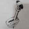
If yours doesn't have the hole for the allen key (some non-genuine ones may not), you can hold the pulley tightly by making a wrench from an old fan belt and a piece of tube. You pass a loop of belt through the tube, and around the pulley, then pull the loop at the other end tight and clamp it. There are ways of devising a screw for tightening it, if you have the facilities and inclination to make it into a proper tool, but for a quick one-off you may find that levering the belt tight and clamping with mole grips against the end of the tube is sufficient.


You then just use it much like a chain or strap type oil filter removal tool. As you apply leverage, the tube will deflect to an angle, which actually pulls the belt tighter, so you just hold the tube and apply a spanner. As Dan says, it will be very tight.


You may even get away with just looping the belt round the pulley and clamping it together tight against the pulley in the vice.


I expect that you can buy a tool much as I have described somewhere, with a screw for tensioning it, but I can't find one right now. However, you could probably use a strap wrench (see link below) if the strap is wide enough to span both pulley flanges, or cut a piece of fan belt just long enough to fill the pulley groove and use the strap wrench on top of that.


Before I knew of the belt trick (can't remember where I got that from, maybe I saw a lever type strap wrench for an oil filter), I once clamped one in a Black and Decker workmate, with the pulley in one of the notches in the jaws. It worked, but does have a high risk of damaging the pulley.


http://www.frost.co....-120mm-cap.html


Edit: See link below which suggests using an impact wrench. That way, with sharp impacts, the inertia of the pulley and alternator armature is what the torque is reacting against, so it does not need to be held.


http://www.peachpart...act-wrench.html


Edited by tiger99, 04 October 2013 - 07:35 AM.


Also tagged with one or more of these keywords: electrical

0 user(s) are reading this topic

0 members, 0 guests, 0 anonymous users