
Nice. Any reason you didn't get new seat base foam..?
The foam isnt in bad shape really, and to be honest im trying (and failing) to keep costs low until i have the car road legal. I'd like some later model SPI seats or something in the future.

Stage One Kit Fitted

Posted 02 July 2018 - 08:10 AM
Nice. Any reason you didn't get new seat base foam..?
The foam isnt in bad shape really, and to be honest im trying (and failing) to keep costs low until i have the car road legal. I'd like some later model SPI seats or something in the future.
Stage One Kit Fitted
Posted 02 July 2018 - 10:04 AM


Stage One Kit Fitted
Posted 02 July 2018 - 10:42 AM


Put's foolish ideas in peoples heads

Posted 02 July 2018 - 12:30 PM
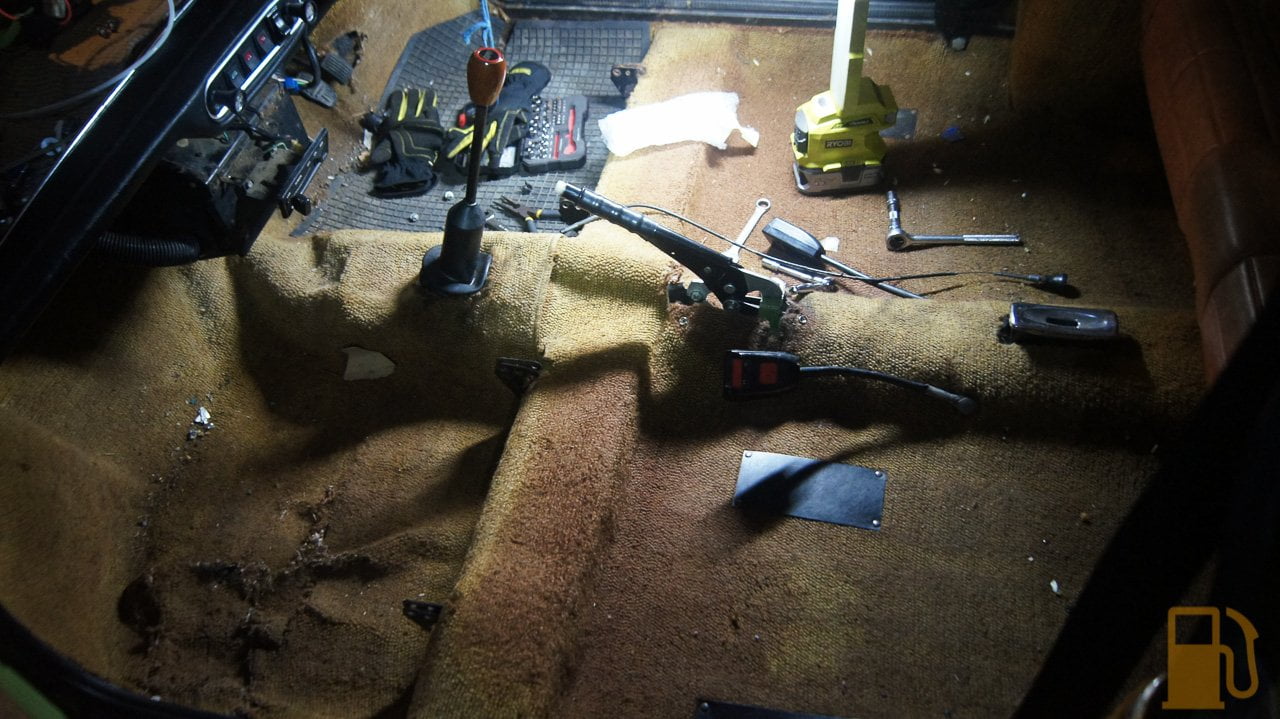
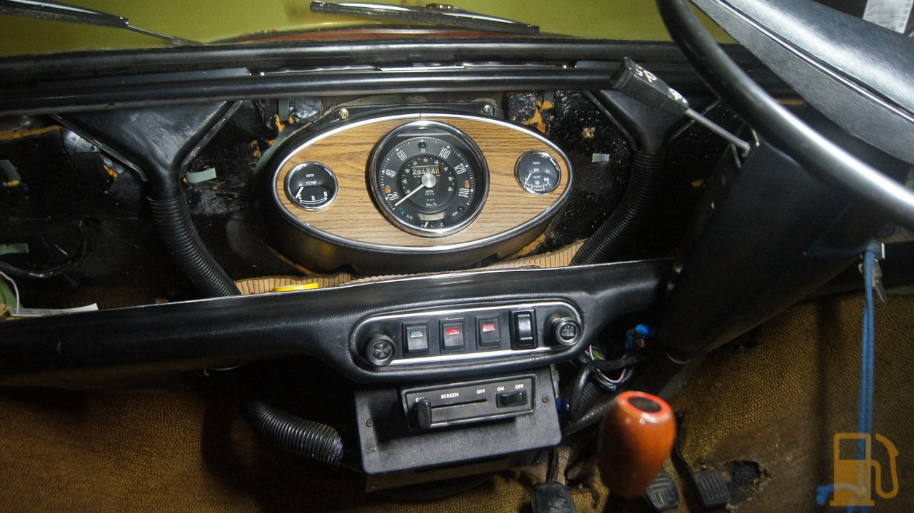
Those carpets don't look terrible, maybe professional carpet cleaners will be able to clean them up nicely.
One Carb Or Two?

Posted 02 July 2018 - 02:12 PM
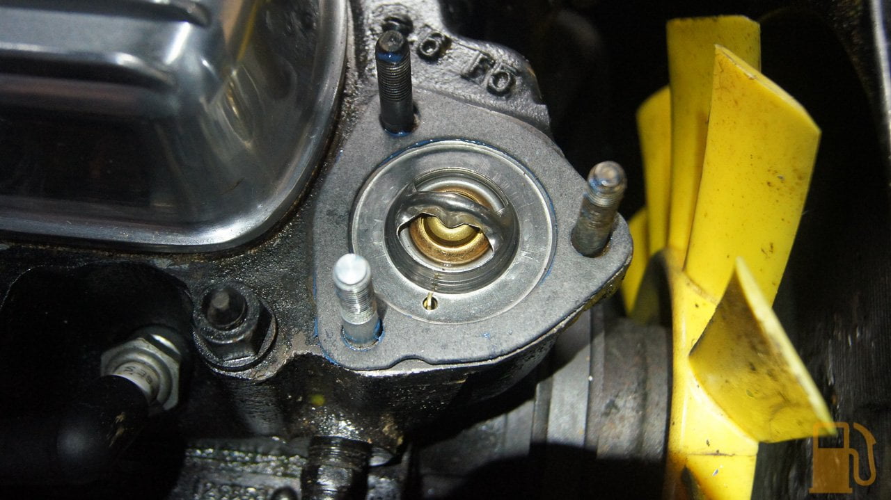
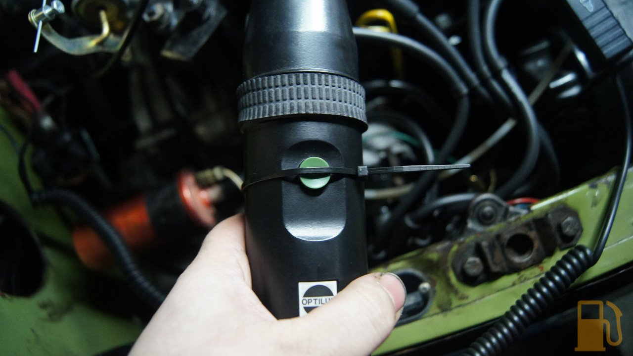
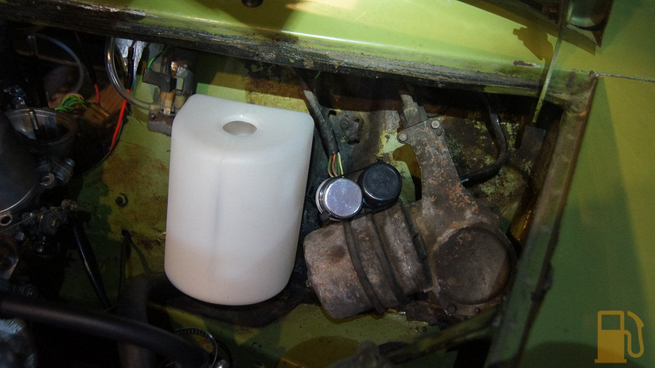
Apparently there has been a bad batch of those heater valves, so i would be carefull with it. Some say ones with MEC (or something similar) stamped on the side are ok
Stage One Kit Fitted
Posted 02 July 2018 - 08:22 PM
Those carpets don't look terrible, maybe professional carpet cleaners will be able to clean them up nicely.
The rear carpets are perfect, just a bit faded. The fronts... well, there aint much good about them. The drivers footwell has a rubber mat glued on over a huge missing part, and the passengers side footwell looks like a tiger got bored.
Apparently there has been a bad batch of those heater valves, so i would be carefull with it. Some say ones with MEC (or something similar) stamped on the side are ok
I have heard there have been issues. Ive had the car up to temp and driven it, and so far no issues, but ill keep an eye on it. I dont recall anything being stamped on mine, but its meant to be one of Minispares own "updated" ones.
Stage One Kit Fitted
Posted 03 July 2018 - 07:18 AM


Stage One Kit Fitted
Posted 03 July 2018 - 10:36 AM


Stage One Kit Fitted
Posted 03 July 2018 - 11:22 AM


Stage One Kit Fitted
Posted 03 July 2018 - 12:09 PM


One Carb Or Two?
Posted 03 July 2018 - 12:29 PM
Nice work.
I did all this work nearly 20 years ago on my beige Mini CIty E before I upgraded to an MPI Cooper S. Got to love injection!
Q
Put's foolish ideas in peoples heads
Posted 03 July 2018 - 12:50 PM
This has been a nice checklist of all the things to fix/service to get a Mini running. Much of it would make great how-to guides. Nicely done.
Stage One Kit Fitted
Posted 03 July 2018 - 01:07 PM
Nice work.
I did all this work nearly 20 years ago on my beige Mini CIty E before I upgraded to an MPI Cooper S. Got to love injection!
Q
Stage One Kit Fitted
Posted 04 July 2018 - 07:42 AM
Edited by kws, 04 July 2018 - 07:44 AM.
Mini Mad

Posted 04 July 2018 - 08:41 AM
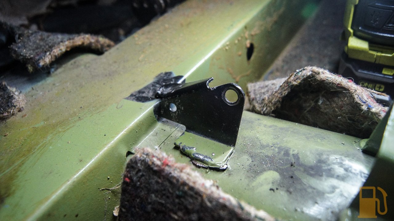
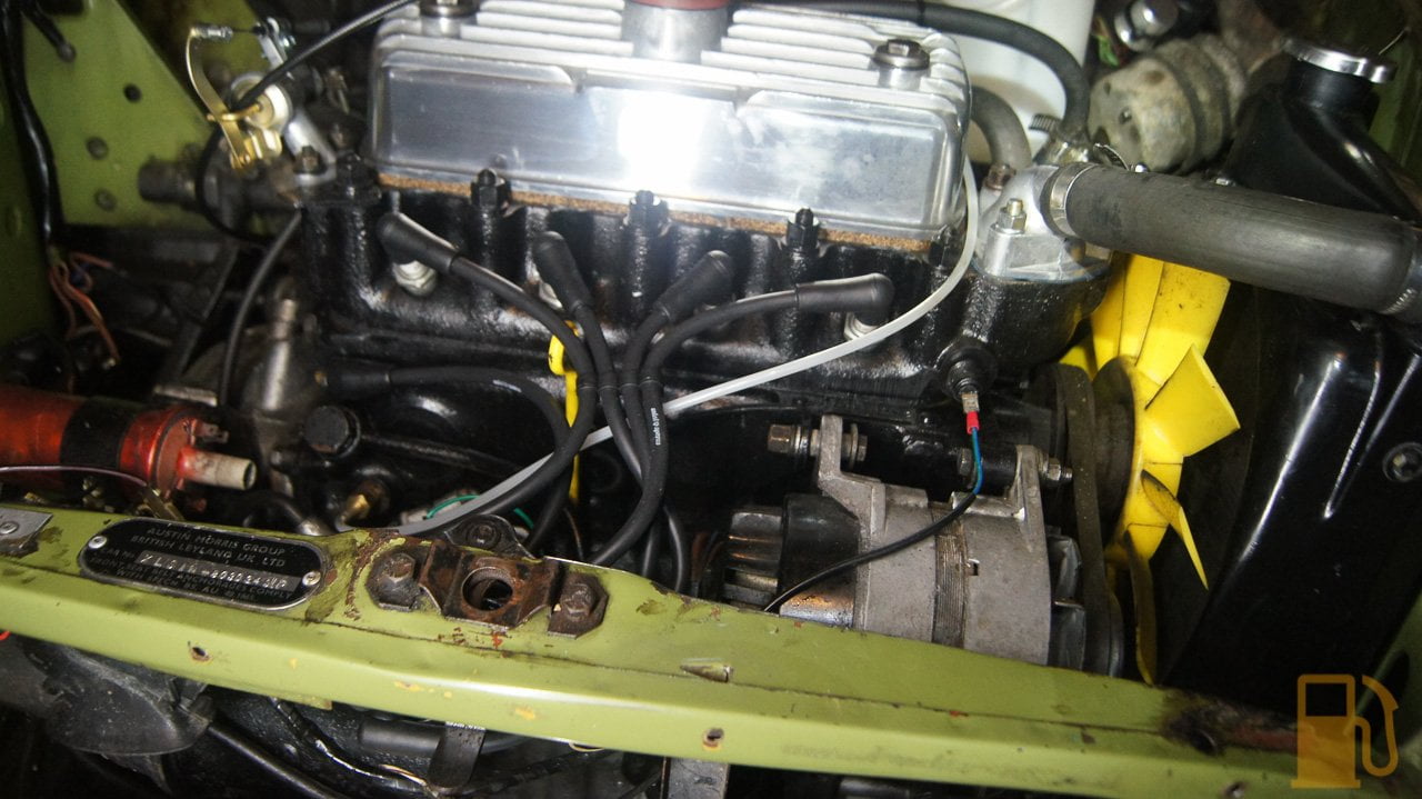
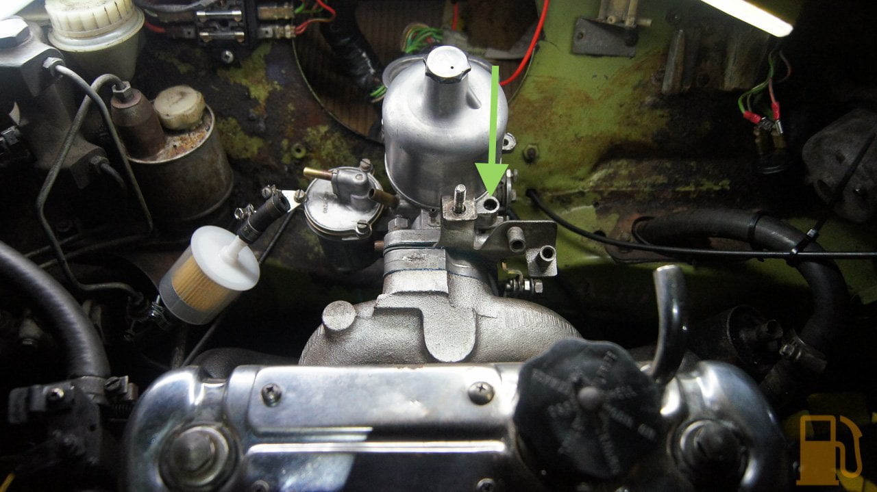
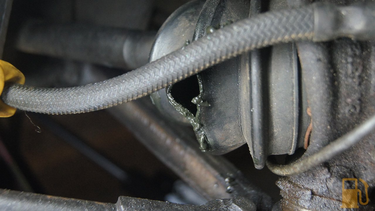
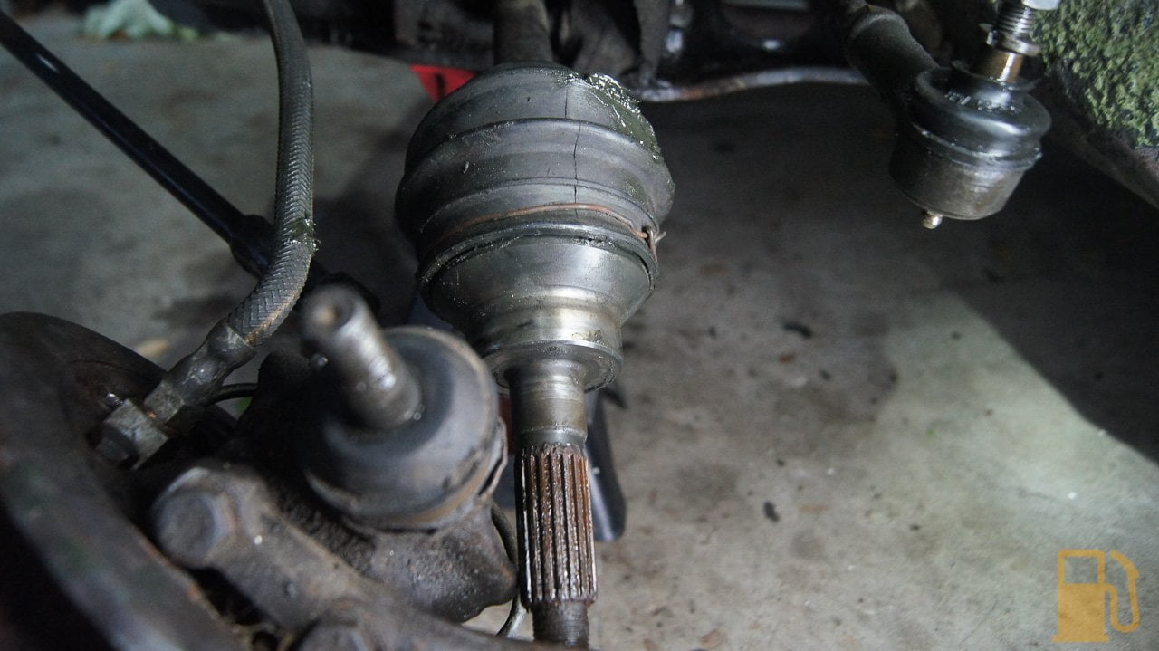
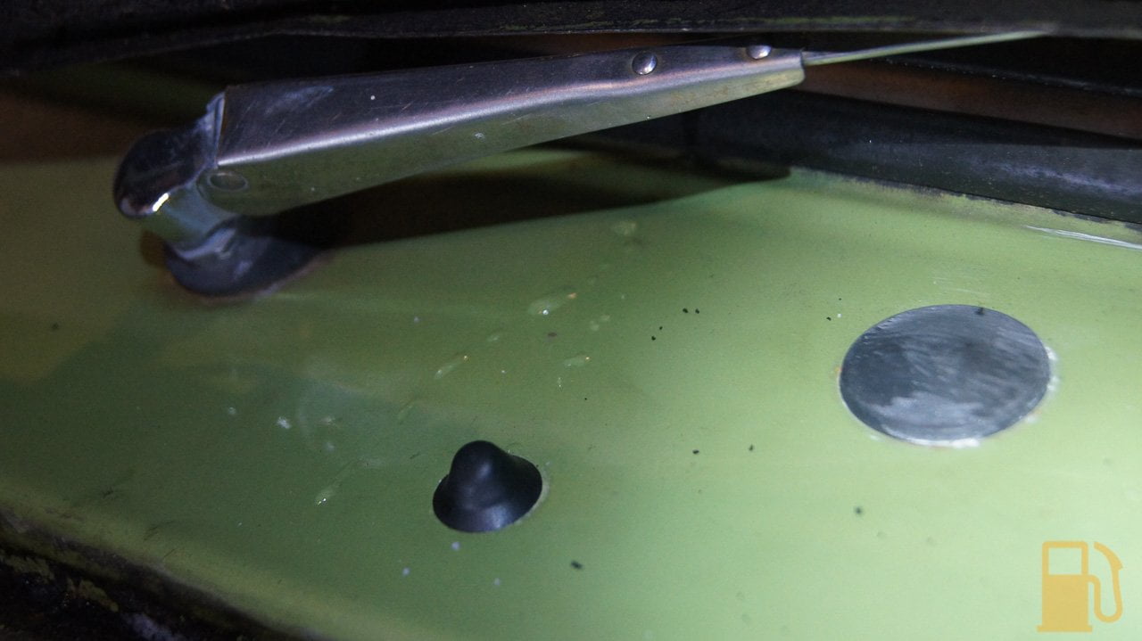
Took the Mini for a quick drive. Compared to the last video, it runs solid now. Pulls well in all gears, and revs out to some undetermined RPM (still waiting on my tacho to arrive). I have a sticky throttle though. Its something to do with my new cable, so hopefully that isnt damaged.I did add an additional ground to the engine today. I find it weird that the only engine ground goes from the engine to the subframe, and then the subframe is rubber mounted. Apparently a bad engine ground can fry the throttle cable as it heats up and melts the inner liner. I hope this hasnt happened, but we will see. Ill pull the cable out and see whats up.Sorry for the mad shakes in the video, but the Mini vibrates just a bit. Dont watch too hard if you get motion sickness.
As above this is a "how to" on pretty much every abused and under maintained mini out there!
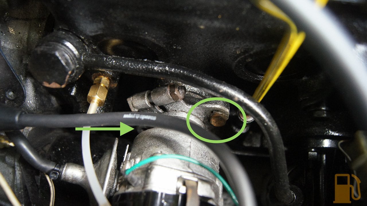
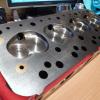
Just looking at the above post the main engine earth should be a lead that goes from the top engine steady bolt to the bulkhead you can see it under the engine steady in the pic below ( I stole this pic so thanks to whoever it is)

and as such shouldnt use the subframe at all
Look forward to the future updates


Projects →
Mini Saloons →
1976 Mini 1000 Le "stripey"Started by cafeclassic , 03 Sep 2025 |
|

|
||
Projects →
Mini Saloons →
Mini Cooper Project - Finally StartsStarted by piphatch , 08 Jan 2025 |
|

|
||
Projects →
Mini Saloons →
1965 Austin Mini Restoration - Canadian Mk1Started by DoubleEh , 14 Nov 2022 |
|

|
||
Projects →
Mini Saloons →
Project Joe - 1991 Mini Mayfair 998Started by Eggers , 02 Jun 2022 |
|

|
||
Projects →
Mini Saloons →
Mpi Dashboad ProblemStarted by mikeprez , 22 Dec 2021 |
|
|
0 members, 0 guests, 0 anonymous users


